49
remains in this mode until the LWT, the compressor load,
or the outdoor temperature changes by a defined amount.
If the change conditions are met the fan control goes back
to the WAITOPT mode followed by the OPTIMZE modes.
• DGT: High Discharge Gas Temperature mode. The VFD
increases the speed of the fan to reduce DGT.
• DP_HIGH, DP_LOW: High Discharge Pressure (DP)
Mode, Low Discharge Pressure Mode: The VFD controls
the speed of the fan to bring SCT (Saturated Condensing
Temperature) into normal operating range.
• OFF: Fans are not running.
• START: Start mode. The frequency of the fans is defined
based on the OAT.
Head Pressure Control (Fixed Speed Fans)
The head pressure is controlled through the Carrier Controller
display by adjusting the number of fans running. The controller
determines the minimum number of fans required to support
unit operation so the unit can run at the most efficient point. At
start up the number of fans on is calculated using OAT. After
60 seconds, an equation is used to determine the number of fan
required based on OAT, EWT, and circuit capacity.
There are additional modes used for fixed speed fans:
DP HIGH
Mode decreases the discharge pressure as fast as possible to
prevent high pressure trips. This mode turns on all fans.
DP HIGH DISCHARGE PRESSURE
Mode avoids high discharge pressure that would cause the com-
pressor to run outside of the compressor envelope. In this mode,
the pressure is controlled to a Discharge Pressure set point.
DGT HIGH
Mode decreases the discharge temperature as fast a possible to
prevent high DGT alarms. This mode turns on all fans.
Sound Optimization
This option runs the chiller at a lower sound level by limiting the
compressor and fan speed. The factors in Table 32 control this
option. The factors are set from the factory and should not be
lowered, as this may cause operational issues. The set points for
this option are on a label inside the door of the control panel.
The compressor speed, fMaxOvrA or B, can be set to a lower
max frequency. The max frequency is limited by the max fre-
quency of the base unit. This option is enabled by changing
fMaxEnA or B to “yes”.
The fan speed limitation is enabled by setting fan_fact to any
value other than 1.00. The factor will be applied to the fan curve
calculation for the fan speed in Hz. If the factor is 0.7, the fan
speed will be 70% of the calculated fan speed. If high saturated
condensing temperature occurs, the controls will override this
feature and increase fan speed to keep the chiller running.
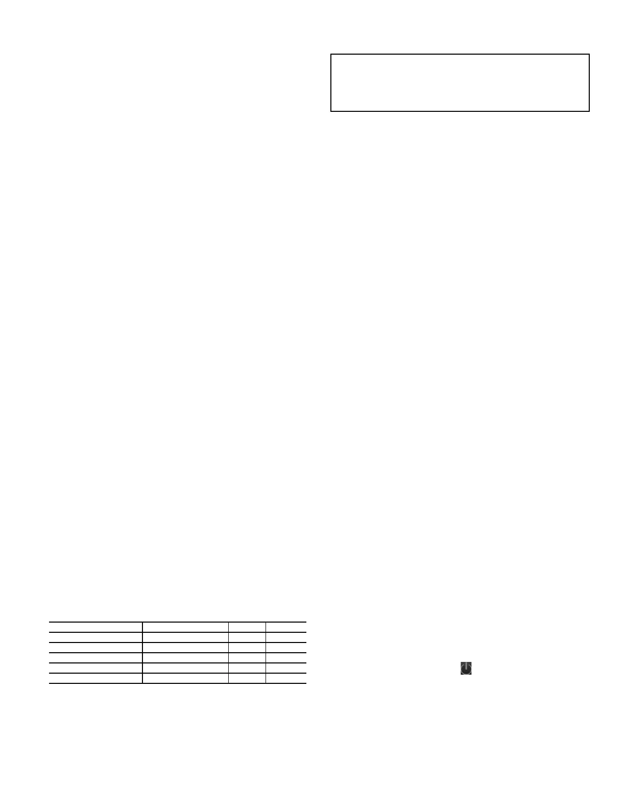
Table 32 — Sound Optimization Factor Settings
PRE-START-UP
Do not attempt to start the chiller until the following checks
have been completed.
System Check
1. Check that auxiliary components, such as the chilled fluid
circulating pump, air-handling equipment, or other equip-
ment to which the chiller supplies liquid are operational.
Consult manufacturer’s instructions. If the unit has field-
installed accessories, be sure all are properly installed and
wired correctly. Refer to unit wiring diagrams.
2. Open compressor suction service valves (if equipped).
3. Open discharge line, liquid line, oil line, and economizer (if
equipped) service valves.
4. Fill the chiller fluid circuit with clean water (with recom-
mended inhibitor added) or other non-corrosive fluid to be
cooled. Bleed all air out of high points of system. If outdoor
temperatures are expected to be below 32°F (0°C), sufficient
inhibited propylene glycol or other suitable corrosion inhibit-
ed antifreeze should be added to the chiller water circuit to
prevent possible freeze-up.
The chilled water loop must be cleaned before the unit is
connected. It is recommended that the chiller pumps be
equipped with a start-up filter screen to remove particulates
from the loop. The start-up filter should be replaced after 24
hours of operation
5. Check tightness of all electrical connections.
6. Electrical power source must agree with unit nameplate.
7. Oil separator heaters must be energized for 24 hours prior to
start-up.
START-UP
Actual Start-Up
Actual start-up should be done only under supervision of a
qualified refrigeration technician.
1. Be sure all oil, suction valves, discharge valves (if equipped)
and liquid line service valves are open.
2. Using the Carrier Controller control, set leaving-fluid set
point (Main Menu
Setpoint Table
Cooling Setpoint
1). No cooling range adjustment is necessary.
3. If optional control functions or accessories are being used,
the unit must be properly configured. Refer to Configuration
Options section for details.
4. Start the chilled fluid pump, if unit is not configured for
pump control (Main Menu
Configuration Menu
Pump Configuration
Evaporator Pumps Sequence =
No Pumps (0)).
5. Complete the Start-Up Checklist to verify all components
are operating properly.
6. Touch the Start/Stop button located in the upper right cor-
ner of the Carrier Controller display and then select Local On.
7. Allow unit to operate and confirm that everything is func-
tioning properly. After unit operation stabilizes, check to see
that leaving set-point Control Point (Main Menu
Set-
point Table
Cooling Setpoint 1) agrees with leaving
fluid temperature (Main Menu
Temperatures
Evap
Leaving Fluid).
FACTOR COMPRESSOR SPEED RANGE DEFAULT
Enable Max Frequency A fMaxEnA no/yes 0 (no)
Enable Max Frequency B fMaxEnB no/yes 0 (no)
Max Frequency Override A fMaxOvrA 30 to 105 75
Max Frequency Override B fMaxOvrB 30 to 105 75
Fan Freq Fctor (0.7-1.1) fan_fact 0.7 to 1.1 1.00
Complete the Start-Up Checklist for 30XV Liquid Chillers
at the end of this publication. The checklist assures proper
start-up of a unit, and provides a record of unit condition,
application requirements, system information, and opera-
tion at initial start-up.
 Loading...


