67
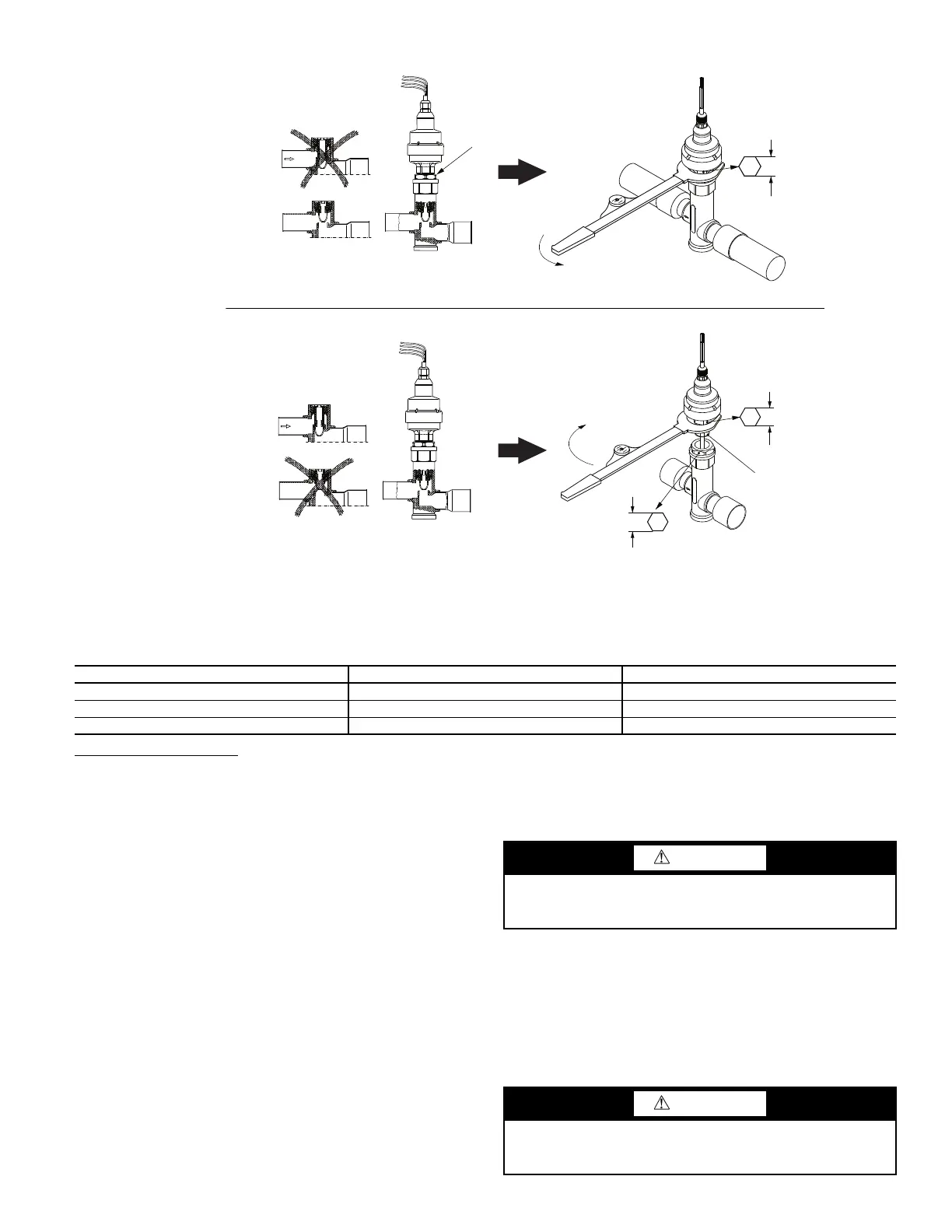
Fig. 61 — Disassembly and Assembly of EXV Motor
Table 41 — Color Indicators When Moisture Is Present in Refrigerant
Liquid Line Service Valve
This valve is located immediately ahead of filter drier, and has a
1
/
4
-in. access connection for field charging. In combination with
compressor discharge service valve, each circuit can be pumped
down into the high side for servicing with plate fin coils. Micro-
channel Heat Exchanger (MCHX) coils have much smaller vol-
ume and cannot accommodate the entire circuit charge.
Compressor Assembly
The 30XV units utilize Greenspeed Intelligence for efficient
operation. The compressor is controlled by a VFD. See Fig. 62
for a view of a typical 06Z compressor. For optimal efficiency
the compressor uses a VI valve to change the inlet area of the
lobes at different loading points. The valve is opened or closed
by a solenoid on the compressor. The control logic looks at cal-
culated parameters to determine the switch point of the valve.
VI VALVE TROUBLESHOOTING
Use the quick test table (Main Menu
Quick Test Table
Circuit X VI) to enable the VI valve output. Enable the valve
output and verify the coil solenoid is energized.
SUCTION VICTAULIC COUPLING INSTALLATION
1. The outside surface of the pipe, between the groove and
the pipe end, must be smooth and free from indentations,
projections (including weld seams), and roll marks to en-
sure a leak-tight seal. All oil, grease, loose paint, and dirt
must be removed. The Victaulic gasket used for refriger-
ant system piping will have a yellow mark on one side of
the gasket lips.
2. Apply a thin coat of Victaulic lubricant or silicone lubricant
to the gasket sealing lips and exterior.
3.
4. Position the gasket over the pipe end. Make sure the gasket
does not overhang the pipe end.
5. Align and bring the two pipe ends together. Slide the gasket
into position and center it between the grooves in each pipe
end. Make sure no portion of the gasket extends into the
groove in either pipe end.
6. Install the housings over the gasket. Make sure the housings’
keys engage the grooves completely on both pipe ends.
COLOR INDICATOR R-134a, 75°F (24°C) (ppm) R-134a, 125°F (52°C) (ppm)
Green — Dry < 30 < 45
Yellow-green — Caution 30-100 45-170
Yellow — Wet >100 >170
CLOSED
OPEN
CLOSED
OPEN
GASKET
OPEN VALVE IN QUICK TEST SUB-MODE BEFORE DISASSEMBLING
EF05BD271 NV 32.5mm
EF05BD331 NV 36mm
50Nm (36 ft-lb)+ 30°
27mm / 1
1
/
16
''
27mm / 1
1
/
16
''
ADAPTER
NOTES:
1. Push down on valve piston to close valve before assembling.
2. After valve is assembled close valve in Quick Test sub-mode or cycle power before opening service valve.
a30-4072
DISASSEMBLY
ASSEMBLY
CAUTION
Always use a compatible lubricant to prevent the gasket
from pinching or tearing during installation. Failure to fol-
low this instruction could result in joint leakage.
CAUTION
Make sure the gasket does not become rolled or pinched while
installing the housings. Failure to follow this instruction could
cause damage to the gasket, resulting in joint leakage.
 Loading...


