19
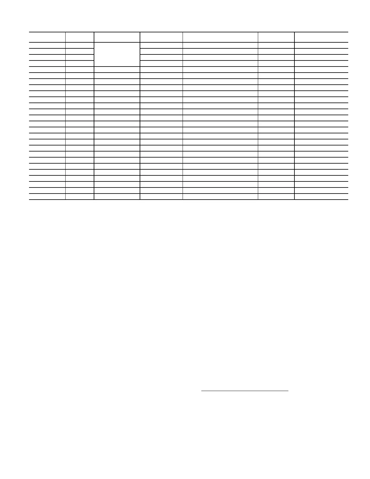
Table 12 — EMM Board Inputs and Outputs
Local Equipment Network
Information is transmitted between modules via a 3-wire com-
munication bus or LEN.
Board Addresses
All boards (except the Carrier Controller display and the Energy
Management Module) have DIP switches to set the address.
Control Module Communication
RED LED
Proper operation of the control boards can be visually checked
by looking at the red status LEDs (Light-Emitting Diodes).
When operating correctly, the red status LEDs will blink in
unison at a rate of once every 2 seconds. If the red LEDs are
not blinking in unison, verify that correct power is being sup-
plied to all modules and that all communication wiring is con-
nected securely. Confirm current version of software installed
on SmartView panel by navigating to Control Identification
Menu (Main Menu
Configuration Menu
HMI Config-
uration Menu
Control Identification Menu
Software
Part Number). If a newer version of the software exists, con-
tact your Carrier service representative service to reload current
software. If the problem still persists, replace the Carrier Con-
troller module. A red LED that is lit continuously or blinking at
a rate of once per second or faster indicates that the board
should be replaced.
GREEN LED
All boards have a green LEN LED which should be blinking
whenever power is on. If the LEDs are not blinking as de-
scribed check LEN connections for potential communication
errors at the board connectors. A 3-wire bus accomplishes
communication between modules. These 3 wires run in parallel
from module to module. They connect to J9 on EMM and
AUX boards, and to J12 or J13 on SIOBs. A valid unit config-
uration must be in the Carrier Controller module for proper
LEN communication.
Carrier Comfort Network
®
Interface
All 30XV units can be connected to the CCN, if desired. The
communication bus wiring is RS-485 Communication Wiring,
CM or CMP rated consisting of a shielded, 3 conductor cable
with drain wire and is field supplied and installed. The system
elements are connected to the communication bus in a daisy
chain arrangement. The positive pin of each system element
communication connector must be wired to the positive pins of
the system elements on either side of it. The negative and signal
ground pins of each system element must also be wired in the
same manner. Wiring connections for CCN should be made at
TB3. See Fig. 22. For noise consideration, communication wir-
ing must be separate and not run in parallel with other wiring.
NOTE: Conductors and drain wire must be 20 AWG (American
Wire Gage) minimum stranded, tinned copper. Individual con-
ductors must be insulated with PVC (Polyvinyl Chloride), PVC/
nylon, vinyl, Teflon
1
, or polyethylene. An aluminum/polyester
100% foil shield and an outer jacket of PVC, PVC/nylon,
chrome vinyl, or Teflon with a minimum operating temperature
range of –20°C to 60°C is required. High temperature applica-
tions may require a higher temperature range. Plenum applica-
tions will require plenum rated cable. Cable voltage require-
ments must match the application.
CHANNEL
IN/OUT
TYPE
BOARD
CONNECTOR
CCN POINT
POINT
DESCRIPTION
I/O POINT
NAME
INPUT/OUTPUT
TYPE
CH 01 AI
J6
— — AI-01 5/10K Thermistor
CH 02 AI SPACETMP Space temperature AI-02 10K Thermistor
CH 03 AI — — AI-03 5/10K Thermistor
CH 04 AI — — AI-04 5/10K Thermistor
CH 05 AI J7A SP_RESET Setpoint reset AI-06 0-5V
CH 06 AI J7B LIM_ANAL Capacity limit AI-07 0-5V
CH 07 AO J8 CAP_T % Total capacity running AO-01 0-10 Vdc
CH 08 DI J4, CH8 OCC_OVSW Occupancy override DI-01 —
CH 09 DI J4, CH9 LIM_SW2 Demand limit SW2 DI-02 —
CH 10 DI J4, CH10 REM_LOCK Remote lockout switch DI-03 —
CH 11a DI J4, CH11A ICE_SW Ice done DI-04 —
CH 11b DI J4, CH11B — — DI-05 —
CH 12 DI J5, CH12 — — DI-06 —
CH 13 DI J5, CH13 — — DI-07 —
CH 14 DI J5, CH14 — — DI-08 —
CH 15 DI J5, CH15 — — DI-09 —
CH 16 DO J2A CP_A Compressor A run status DO-01 Triac
CH 17 DO J2A CP_B Compressor B run status DO-02 Triac
CH 18 DO J2A — — — —
CH 19 DO J2A — — — —
CH 20 DO J2B — — — —
CH 21 DO J2B — — — —
CH 22 DO J2B — — — —
CH 23 DO J2B — — — —
CH 24 DO J3 SHUTDOWN Shutdown relay DO-09 Relay
CH 25 DO J3 ALERT Alert relay DO-10 Relay
1. Teflon is a registered trademark of DuPont.
 Loading...


