68
7. Install the bolts, and thread a nut finger-tight onto each bolt.
For couplings supplied with stainless steel hardware, apply
an anti-seize compound to the bolt threads. Make sure the
oval neck of each bolt seats properly in the bolt hole.
8. Tighten the nuts evenly by alternating sides until metal-to-
metal contact occurs at the bolt pads. Make sure the hous-
ings’ keys engage the grooves completely. It is important to
tighten the nuts evenly to prevent gasket pinching.
9. Visually inspect the bolt pads at each joint to ensure metal-
to-metal contact is achieved.
COMPRESSOR OIL SYSTEM
Each compressor/circuit has its own oil system which includes an
oil filter, oil solenoid, check valve, oil level switch, oil separator
heater, oil pressure transducer, and an oil shut-off valve. A typical
oil system is shown in Fig. 63 and 64. See Table 42 for required oil
quantity per circuit, initially included from the factory.
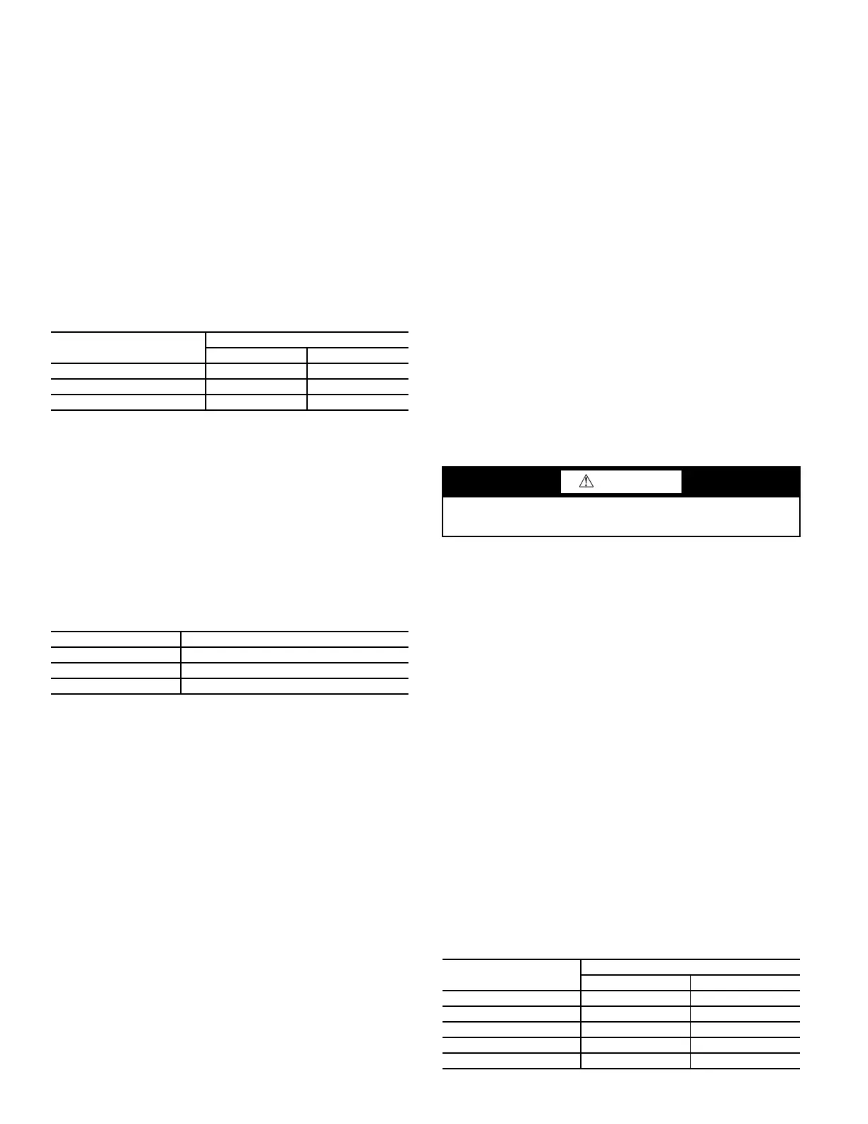
Table 42 — Unit Oil Quantities
Oil Charge
When additional oil or a complete charge is required it must
meet the following specifications:
• . .Manufacturer . . . . . . . . . Emkarate RL220XL
• Oil Type . . . . . . . . . . . . . Inhibited polyolester-based syn-
thetic compressor lubricant for
use with screw compressors.
• ISO Viscosity Grade . . . 220
Do not reuse drained oil or any oil that has been exposed to the
atmosphere.
Oil is available in the following quantities from your local
Carrier representative:
If unsure if there is low oil charge in the system, follow the
steps below:
1. If the unit shuts off repeatedly from a low oil level alert, it
may be an indication of inadequate oil charge: however, it
could also indicate the oil is not being reclaimed from the
low-side of the system.
2. Run the circuit at full load for 1
1
/
2
hours.
NOTE: An adequate load must be available.
3. After running the unit for 1
1
/
2
hours at full load, stop the unit.
Check the oil level in the oil separator sight glass. An oil lev-
el should be visible in the upper sight glass. If level is not
visible, the unit is low on oil charge.
4. Add oil until the oil is at the center of the upper sight glass.
Make sure not to add oil beyond this level as excess oil will
be carried out of the oil separator into the system and might
lead to system instabilities at certain conditions.
5. The factory oil charging stations are programed to add pre-
cise amount of oil to the oil separator and if the oil level
while inspection shows higher than middle of the top sight
glass then it could be due to refrigerant mixed in it. Do not
remove any oil.
Add oil to the oil separator using the
1
/
4
-in. access fitting on
the side of the separator.
NOTE: To facilitate the oil charging process, ensure that
the unit is not running when adding oil. The system is un-
der pressure even when the unit is not running, so it is nec-
essary to use a suitable pump to add oil to the system. Us-
ing a suitable pump, add
1
/
2
gal (1.9 L) of oil to the system.
Continue adding oil in
1
/
2
gal (1.9 L) increments until the
problem is resolved, up to a maximum of 1.5 gal (5.7 L).
6. Larger units (350 Circuit A and 400-500 ton units) will not
have sight glasses for reference. The same procedure should
be followed. To check for oil in the evaporator, determine the
approach, LWT - SST. This should be less than 10°F for
fresh water for a circuit running in steady state condition at
full load. If over this amount, there is still oil logged in the
evaporator. Continue to run at full load to remove it. If the
approach is low (less than 6) and there are low oil level
alarms, add 0.5 gal. to the circuit.
Oil Filter Maintenance
Each circuit has one oil filter bolted externally to the compres-
sor. Oil line pressure drop is monitored by the control. Oil line
pressure drop is calculated by subtracting oil pressure (OPT)
from discharge pressure (DPT). If the oil line pressure drop ex-
ceeds 30 psig (206.8 kPa) for 5 minutes the control will gener-
ate a High Oil Filter Pressure Drop alert. The High Oil Filter
Pressure Drop alert will not shut down the compressor, but in-
stead indicates that the oil filter is dirty. If oil pressure line
losses exceed 50 psig (344.7 kPa) for more than 30 seconds
then the control will shut down the circuit on Maximum Oil
Filter Differential Pressure Failure.
Replacing the Oil Filter
Close the oil service valves on either side of filter by removing
the cap and closing the valve. One is connected to the oil filter
and the other is mounted on the compressor. Connect a
charging hose to the ¼-in. access fitting port located between
the filter and compressor. Bleed off the oil located in this sec-
tion. A quart of oil is typically removed during this process.
Unscrew the nuts on either side of the filter. Remove the filter
and install the new one. Make sure to remove the plastic caps
from the new filter before installation. Take care not to lose or
damage the new O-rings on the new filter. Draw a vacuum at
the service port. Remove the charging hose and open the oil
service valves. Replace caps on access port and service valves.
Check both fittings for leaks.
Evaporator Service
The 30XV units use flooded style evaporators.
ISOLATION VALVE
The isolation valve is a factory-installed option for 30XV units.
The option includes a butterfly-style suction service valve on the
suction lines, and manual ball valves on discharge, evaporator
inlet and economizer lines. The butterfly valve is connected to
the suction line by Victaulic connections. See Fig. 65 and 66 for
details on the butterfly suction service valve operation. The
valve locks into place when fully opened or fully closed. See
Table 43 for compressor usage.
Table 43 — Compressor Usage
30XV UNIT SIZE
OIL CHARGE (gal, [liters])
Circuit A Circuit B
140-325 5.5 [20.8] 5.5 [20.8
350 7.5 [28.4] 5.5 [20.8
400-500 7.5 [28.4] 7.5 [28.4]
QUANTITY TOTALINE PART NO.
1 Quart P903-2325
1 Gallon P903-2301
5 Gallon P903-2305
CAUTION
Compressor oil is pressurized. Use proper safety precautions
when relieving pressure.
30XV UNIT SIZE
COMPRESSOR MODELS
CKT A CKT B
140 - 200 06ZCE1 06ZCE1
225 06ZFC2 06ZCE1
250 - 325 06ZFC2 06ZFC2
350 06ZJG3 06ZFC2
400-500 06ZJG3 06ZJG3
 Loading...


