47
ALARM EQUIPMENT PRIORITY
The ComfortVIEW software uses the equipment priority value
when sorting alarms by level. The purpose of the equipment
priority value is to determine the order in which to sort alarms
that have the same level. A priority of 0 is the highest and
would appear first when sorted. A priority of 7 would appear
last when sorted. For example, if two chillers send out identical
alarms, the chiller with the higher priority would be listed first.
The default is 4. This variable can only be changed when using
the ComfortVIEW software, or Network Service Tool. This
variable cannot be changed with the Carrier Controller display.
To configure this option with the Network Service Tool, navi-
gate to point EQP_TYP in table ALARMDEF.
COMMUNICATION FAILURE RETRY TIME
This variable specifies the amount of time that will be allowed
to elapse between alarm retries. Retries occur when an alarm is
not acknowledged by a network alarm acknowledger, which
may use either ComfortVIEW software or TeLink. If acknowl-
edgment is not received, the alarm will be re-transmitted after
the number of minutes specified in this decision. This variable
can only be changed when using the ComfortVIEW software,
or Network Service Tool. This variable cannot be changed with
the Carrier Controller display. To configure this option with the
Network Service Tool, navigate to point RETRY_TM in table
ALARMDEF.
RE-ALARM TIME
This variable specifies the amount of time that will be allowed
to elapse between re-alarms. A re-alarm occurs when the con-
ditions that caused the initial alarm continue to persist for the
number of minutes specified in this decision. Re-alarming will
continue to occur at the specified interval until the condition
causing the alarm is corrected. This variable can only be
changed when using the ComfortVIEW software, or Network
Service Tool. This variable cannot be changed with the Carrier
Controller display. To configure this option with the Network
Service Tool, navigate to point RE_ALARM in table
ALARMDEF.
ALARM SYSTEM NAME
This variable specifies the system element name that will ap-
pear in the alarms generated by the unit control. The name can
be up to 8 alphanumeric characters in length. This variable can
only be changed when using the ComfortVIEW™ software or
Network Service Tool. This variable cannot be changed with
the Carrier Controller display. To configure this option with the
Network Service Tool, navigate to point ALRM_NAM in ta-
ble ALARMDEF.
Daylight Savings Time Configuration
The 30XV chiller with Greenspeed
®
Intelligence control con-
tains software which can automatically correct for daylight sav-
ings time. This software is accessible from the Carrier Controller
display, ComfortVIEW software, or Network Service Tool.
To enable this feature, Daylight Savings Select must be set to
1. The start of daylight saving must be configured by setting
the Month, Day of Week, and Week of Month. The end for
Daylight Saving must also be configured. To configure this op-
tion with the Carrier Controller display, see Table 30.
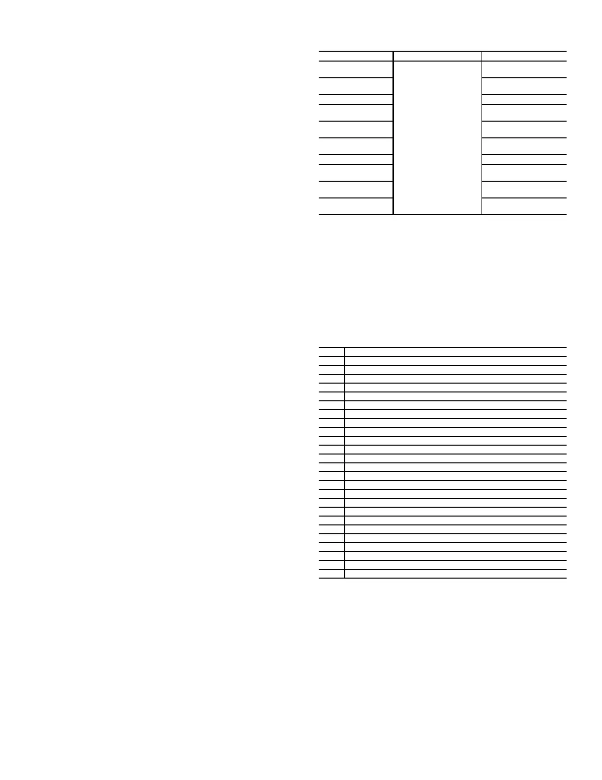
Table 30 — Daylight Savings Time Configuration
Capacity Control Overrides
The following capacity control overrides (Main Menu
Maintenance Menu
Capacity Control
Override Capaci-
ty Nb A, B) will modify the normal operation routine. If any of
the override conditions listed below is satisfied, the override
will determine the capacity change instead of the normal con-
trol. Overrides are listed by priority order and are often linked
to unit operating modes. See Table 31 for a list of capacity con-
trol overrides. See the Operating Modes section on page 56 for
more information regarding operating modes.
Table 31 — Capacity Control Overrides
Override #2: Low Suction Pressure
This override is activated when the Expansion Valve (EXV) is
not in DSH (discharge superheat) mode and the Saturated Suc-
tion Temperature (SST) goes below 13.25°F (–10.4°C) for wa-
ter or below (13.25°F – (34°F – Brine Freeze Setpoint)) for
units configured with brine. The controller at this point starts to
unload the unit until the SST exceeds 34°F (1.1°C).
Override #6: EWT < Control Point
This override stops the compressors without alarms.
Override #7: Ramp Loading
No capacity increase will be made if the unit is configured for
ramp loading and the rate of change of the leaving water is
greater than Ramp Loading Rate.
DISPLAY NAME PATH VALUE
Activate
Main Menu
Configuration Menu
Broadcast Menu
Brocasts
1 or 2
Default = 2
Daylight
Savings Select
Enable
Default = Disable
Entering
Month
Enter Starting Month for
Daylight Saving
Day of Week
(1=Monday)
Enter the Day of the Week
Daylight Saving Starts
Week of Month
Enter Week of the Month
Daylight Saving Starts
Leaving
Month
Enter Ending Month for
Daylight Saving
Day of Week
(1=Monday)
Enter the Day of the Week
Daylight Saving ends
Week of Month
Enter Week of the Month
Daylight Saving ends
NO. DESCRIPTION
0 Normal Operation
2 Low Suction Pressure
6 EWT < control point
7 Ramp Loading
9 Demand Limit Reached
10 Flow switch is open
11 Customer Interlock is closed
12 Flow Available Delay
14 Low LWT
15 Compressor Disabled
16 High Discharge Pressure
23 Low SP
25 Oil Recovery
34 Low SST
53 ON-OFF-ON Delay
56 Evaporator Heater Isolation Valve Opening Delay
59 Low Oil Level
62 High Compressor Motor Temperature
66 High Discharge Gas Temperature
67 DGT Off Protection
70 Low Refrigerant Protection
71 Low Refrigerant Protection
77 Oil Pressure at Start
78 Bad VFD Spd At Start
91 Demand Limit
 Loading...


