45
EXTERNALLY POWERED (4 TO 20 MA) DEMAND LIMIT
The energy management module is required for 4 to 20 mA
demand limit control. An externally powered 4 to 20 mA sig-
nal must be connected to TB6-1 and TB6-2. This signal is
read by a transducer type (0 to 5 vdc) on the EMM board via
a field-installed 0.5 W 250-ohm resistor.
To configure demand limit for 4 to 20 mA control based on unit
capacity, one parameter must be configured. The parameter is
Demand Limit Type Select. The value of the capacity limit will
vary linearly for 0% to 100% based on the input signal where 4
mA is 100% and 20 mA is 0% of total unit capacity.
To configure this option with the Carrier Controller display:
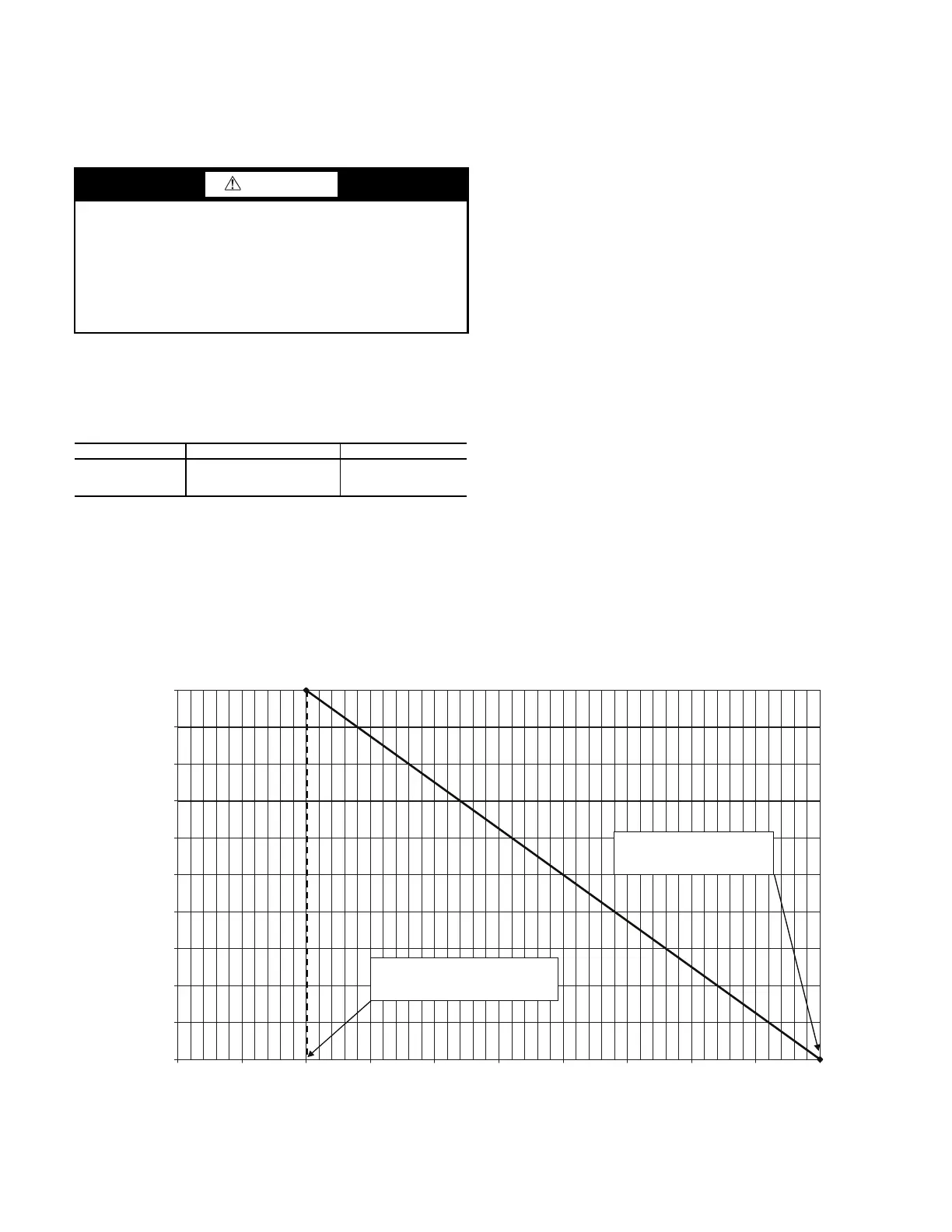
In the example in Fig. 43, a 4 mA signal is Demand Limit
100% and a 20 mA Demand Limit signal is 0%. The 4 to 20
mA signal is connected to TB6-1 and TB6-2. The demand limit
is a linear interpolation between the two values entered. If the
machine receives a 12 mA signal, the machine controls will
limit the capacity to 50%.
CCN LOADSHED CONTROLLED DEMAND LIMIT
To configure Demand Limit for CCN Loadshed control, the unit
Operating Type Control must be in CCN control. With the Carrier
Controller display, the machine must be started in Network Mode.
Network control can be executed from the GENUNIT table.
The unit must be controlled by a Chillervisor module. The
Chillervisor module can force the demand limit variable and
directly control the capacity of the machine. Additionally, the
unit’s set point will be artificially lowered to force the chiller to
load to the demand limit value.
Machine Start Delay
An option to delay the start of the machine is available. This
parameter is useful in keeping multiple machines from starting
at the same time in case of a power failure. The parameter has a
factory default of 1 minute. This parameter also has a role in
the timing for a chilled water flow switch alarm. To configure
this option with the Carrier Controller display, select Main
Menu
Configuration Menu
General Configuration and
select Unit Off to On Delay.
Fast Loading
The Fast Capacity Recovery function allows for an accelerated
unit start-up. This is especially useful following brief power out-
ages at data centers where rapid restart can keep data center op-
erating. This should not be used on normal comfort cooling ap-
plications. To activate the Fast Capacity Recovery, go to Main
Menu
Configuration Menu
Service Parameters and set
Fast Capacity Recovery. The available options are as follows:
• Disabled (normal loading sequence): Follows the set delays
for unit and circuit start up
• Quick start Load - (Quick Start Loading): With Flow es-
tablished, ignores Capacity Control Override #53 (ON-
OFF-ON Delay)
• Fast Capacity Recov (Fast Capacity Recovery): With Flow
established, ignores Capacity Control Override #53 (ON-
OFF-ON Delay), and allows both compressors to start at
the same time (with a 10-second delay between starts)
NOTE: Unit cannot operate with Ramp Loading enabled if
Fast Capacity Recovery is set to Quick start Load or Fast Ca-
pacity Recov.
Fig. 43 — Example: 4 to 20 mA Demand Limit
CAUTION
Care should be taken when interfacing with other control sys-
tems due to possible power supply differences such as a full
wave bridge versus a half wave rectification. Connection of
control devices with different power supplies may result in
permanent damage. Carrier Controller controls incorporate
power supplies with half wave rectification. A signal isola-
tion device should be utilized if the signal generator incorpo-
rates a full wave bridge rectifier.
DISPLAY NAME PATH VALUE
Demand Limit
Type Select
Main Menu
Configuration Menu
General Configuration
Default = 0 (None)
4 to 20mA Control = 2
0
10
20
30
40
50
60
70
80
90
100
12 14 16 18
20
mA Demand Limit Signal
% Demand Limit
0
2
4 6
8 10
mA for Demand Limit = 100%
(lim_mx)
mA for Demand Limit = 0%
(lim_ze)
a30-5883
 Loading...


