5-2
Cisco ASR-920-24SZ-IM, ASR-920-24SZ-M, ASR-920-24TZ-M Aggregation Services Router Hardware Installation Guide
Chapter 5 Troubleshooting
Pinouts
GPS Port Pinout
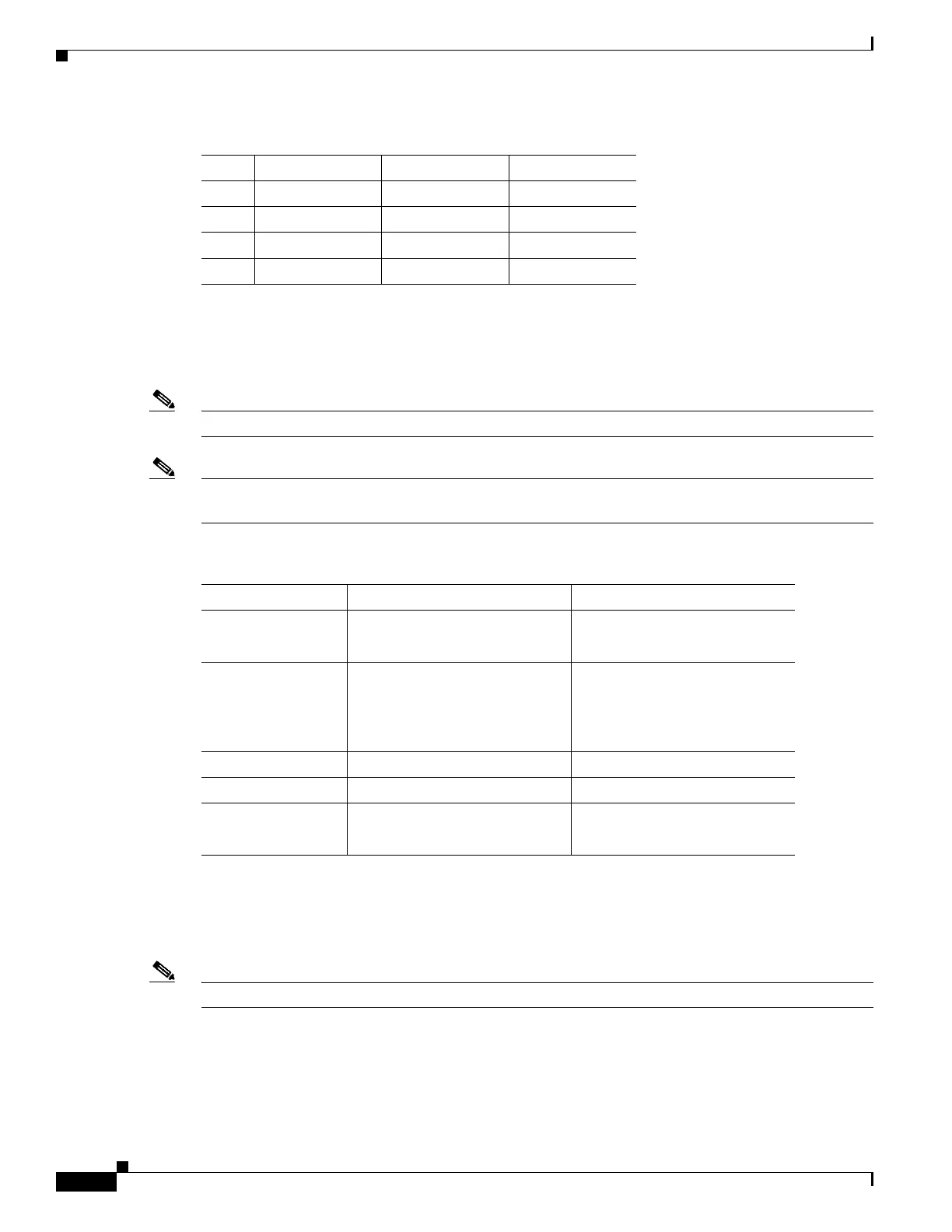
Table 5-2 summarizes the GPS port pinouts.
Note GPS port is supported only on Cisco ASR-920-24SZ-IM Router.
Note The 10 Mhz and 1 PPS interfaces can be configured as input or output using Cisco IOS CLI commands.
For more information, see the Cisco ASR 920 Series Aggregation Services Router Configuration Guide.
Time-of-Day Port Pinouts
Table 5-3 summarizes the ToD/1-PPS port pinouts.
Note ToD port is supported only on Cisco ASR-920-24SZ-IM Router.
5 TX Tip Output TX Tip
6 — — Not used
7 — — Not used
8 — — Not used
Table 5-1 BITS Port Pinouts
Pin Signal Name Direction Description
Table 5-2 GPS Port Pinout
10 Mhz (input and output) 1PPS (input and output)
Waveform Input—Sine wave
Output—Square wave
Input—Pulse shape
Output—Pulse shape
Amplitude Input— > 1.7 volt p-p
(+8 to +10 dBm)
Output— > 2.4 volts TTL
compatible
Input— > 2.4 volts TTL
compatible
Output— > 2.4 volts TTL
compatible
Impedance 50 ohms 50 ohms
Pulse Width 50% duty cycle 26 microseconds
Rise Time Input—AC coupled
Output—5 nanoseconds
40 nanoseconds
 Loading...