1-14
Cisco ASR-920-24SZ-IM, ASR-920-24SZ-M, ASR-920-24TZ-M Aggregation Services Router Hardware Installation Guide
Chapter 1 Overview
Cisco ASR 920 Series Routers Features
CPU Management Port LEDs
The LED for the 10/100/1000 Management port is integrated on the connector itself. There are two LEDs
in the connector—the LED on the left indicates the Link/Activity status and the LED on the right
indicates the duplex status of the link.
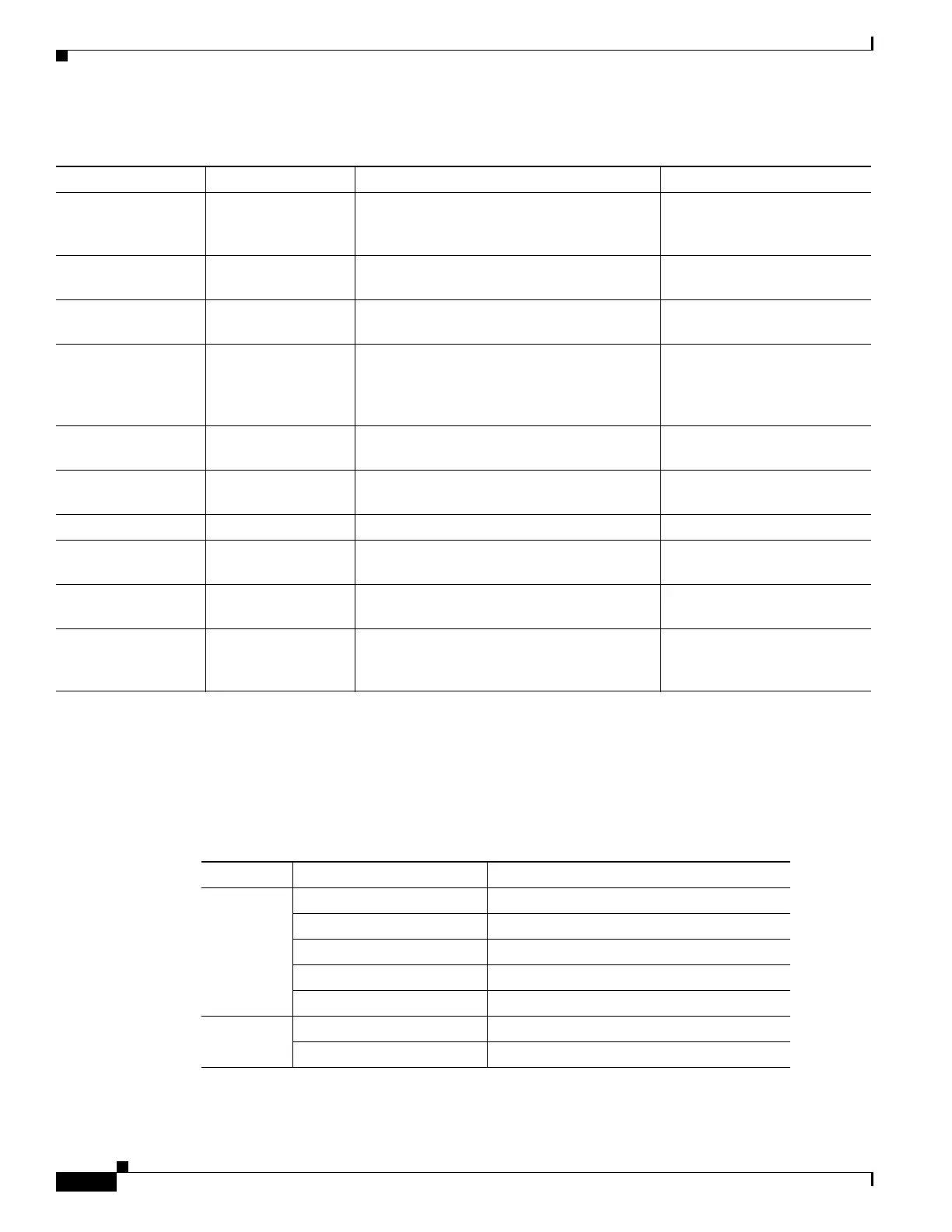
Table 1-5 PWR and STAT LED Indications
PWR LED State STAT LED state Indication Comment
Amber Off Power in the system is all right and FPGA
configuration is taking place.
Permanent Amber/Off
indicates FPGA configuration
failure.
Amber Red FPGA Image Validation Error. System is in unresponsive
state. No console messages.
Flashing Amber and
Green alternatively
Amber Upgrade FPGA image error, continuing with
Golden FPGA image.
—
Flashing Amber and
Green alternatively
Off FPGA configuration successful and Digital
code signing successfully validated FPGA
image. Digital code signing passed the
control to Microloader to boot ROMMON.
—
Flashing Amber and
Green alternatively
Red Digital code signing reported failure in
ROMMON image validation.
System is in unresponsive
state. No console messages.
Green Flashing Amber ZTP process has begun. Both LEDs turn Green once
provisioning is complete.
Green Off IOS-XE image is booting.
Green Green Successfully booted and system is operating
normally.
—
Green Amber A minor alarm or synchronization is in
Holdover or free-running mode
—
Green Red A major or critical alarm (high temperature
reported for any sensor) or multiple fan
failure.
—
Table 1-6 CPU Management Port LED Indication
LED LED State Indication
Left Green Link up in 1000 Mbps
Blinking Green Activity in 1000 Mbps
Amber/Orange Link up in 100/10 Mbps
Blinking Amber/Orange Activity in 100/10 Mbps
Off Link down
Right Green Link up in full duplex
Off Link up in half duplex
 Loading...