Vector Sensor Reference Manual 122
Appendix B - Interface
This appendix provides information on interfacing the various aspects of your Vector Sensor.
The main purpose of the Vector Sensor is to provide highly accurate heading information derived
from GPS measurements. The secondary purpose is differentially corrected positioning using its
redundant differential receivers.
The following sections detail how to interface your Vector Sensor depending on your application.
GPS NMEA Output
When operating the Vector Sensor as a heading and differential positioning tool, the data output
from either Vector Sensor communication port is NMEA data that provides a variety of
information, such as heading, position, speed, satellites tracked, and more. This is the normal data
output and mode of operating the Vector Sensor.
To establish communications between the Vector Sensor and your data logging or navigation
device in this mode of operation, you must:
• Connect Pin-2 - transmit (TX) of either Port A or B to the receive pin (RX) of the data logging or
navigation device.
• Connect Pin-3 - receive (RX) of either Port A or B to transmit pin (TX) of the other device if it is able to
configure the Vector Sensor system. Otherwise, this connection is optional.
• Connect Pin-5 - signal ground of either Vector Sensor port to the signal return or of the external device.
This configuration is also used for the output of RTCM data and binary messages from either serial
port.
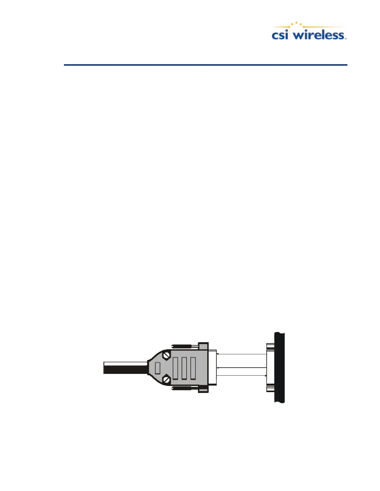
Figure B-1 illustrates the required interface between the Vector Sensor and an external device.
2 TX
3 RX
NMEA
GND
TX
RX
Port A / B
Figure B-1 GPS Data Interface
 Loading...