Vector Sensor Reference Manual 42
Table 2-4 Display Only Pin-out, RS-232C Interface Level
Pin Signal Description
2 TXD Programming output
3 RXD Programming input
5 Sig. Ground Signal return / power ground
6 3.3 VDC Power output
9 5 VDC Power output
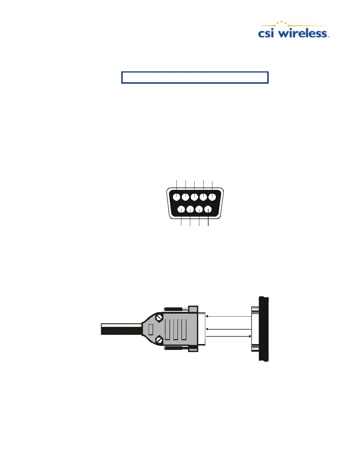
Figure 2-2 displays the numbering scheme for extension cable’s DB9 socket connectors (female).
The associated numbering for the plug connector (male) is a mirror reflection of scheme showed
in this figure.
Figure 2-2 DB9 Socket Numbering
Figure 2-3 and 2-4 illustrate the standard interface for the Vector Sensor when interfaced to an
external device with either the Port A or Port B serial ports.
2 TX
3 RX
NMEA/Binary/
RTCM
5 GND
GND
TX
RX
SERES Port A
RTCM
Figure 2-3 Port A Interface
 Loading...