Vector Sensor Reference Manual 40
• Secure along the cable route using plastic tie wraps.
Caution - The Vector Sensor receiver provides 5 VDC across the antenna ports.
Connection to incompatible devices may result in damage to equipment.
Warning - Improperly installed cables near machinery can be dangerous.
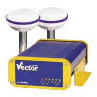
2.7.4 Connecting the CDA-RTK and MBL-3 Antennas
The two CDA-RTK Antennas and the MBL-3 antenna connect to the Vector Sensor using the
supplied TNC-male-to-TNC-male antenna cables. To connect the CDA-2MAX Antenna to the
DGPS MAX:
• Connect the CDA-RTK antenna labelled Primary RF to the primary GPS RF port on the Vector Sensor
• Connect the CDA-RTK antenna labelled Secondary RF to the secondary GPS RF port on the Vector
Sensor
• Connect the MBL-3 antenna to the Beacon RF port on the Vector Sensor
Caution - Be sure to always connect the antennas to the Vector Sensor before you
turn the receiver on.
2.7.5 Powering the Vector Sensor
The first step to powering the Vector Sensor is to terminate the wires of the power cable as
required. There are a variety of power connectors and terminals on the market from which to
choose, depending on your specific requirements
Caution - do not apply a voltage higher than 40 VDC as this will damage the receiver
and void the warranty
To interface the Vector Sensor power cable to the power source:
• Connect the red wire of the cable’s power input to DC positive (+)
• Connect the black wire of the cable’s power input to DC negative (-)
The Vector Sensor smart antenna features reverse polarity protection to prevent damage if the
power leads are accidentally reversed. The Vector Sensor, however, does not function with
reverse polarity.
A 3.0 A fast-blow fuse, situated in-line of the power input of the extension cable and protects the
Vector Sensor receiver from power surges. The fuse container should remain accessible after
installation.
Once the Vector Sensor system has been installed, you’re ready to turn the system on by applying
power to it. The Vector Sensor smart antenna will start when and acceptable voltage is applied to
the power leads of the extension cable. Be careful not to provide a voltage higher than the input
range as this will damage the antenna.
 Loading...