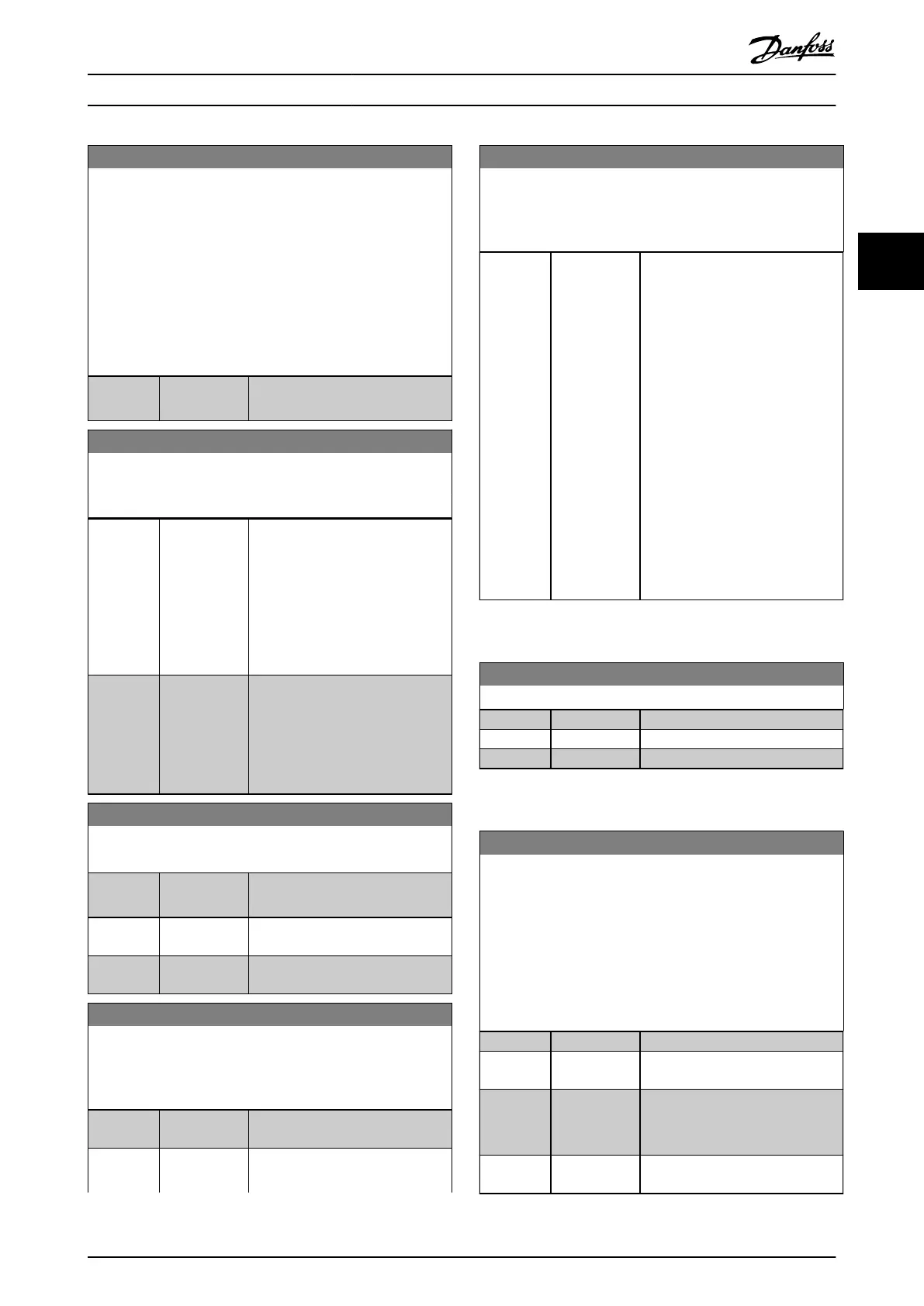
8-05 End-of-Timeout Function
Select the action after receiving a valid control word following a
timeout.
This parameter is active only when parameter 8-04 Control
Timeout Function is set to:
•
[7] Set-up 1.
•
[8] Set-up 2.
•
[9] Set-up 3.
•
[10] Set-up 4.
Option: Function:
[1] * Resume set-up Resumes the set-up that was active
before the timeout.
8-06 Reset Control Timeout
This parameter is active only when option [0] Hold set-up has
been selected in parameter 8-05 End-of-Timeout Function.
Option: Function:
[0] * Do not reset Retains the set-up specied in
parameter 8-04 Control Timeout
Function:
•
[7] Set-up 1.
•
[8] Set-up 2.
•
[9] Set-up 3.
•
[10] Set-up 4.
[1] Do reset Restores the frequency converter to
the original set-up following a
control word timeout. The
frequency converter performs the
reset and immediately reverts to
the [0] Do not reset setting.
8-07 Diagnosis Trigger
Not all eldbusses support the diagnosis functions.
Option: Function:
[0] * Disable Send no extended diagnosis data
(EDD).
[1] Trigger on
alarms
Send EDD after alarms.
[2] Trigger alarm/
warn.
Send EDD after alarms or warnings.
8-08 Readout Filtering
Use this function if the speed feedback value readouts on the
eldbus uctuate. Select [1] Motor Data LP-Filter if the function is
required. A power cycle is required for changes to take eect.
Option: Function:
[0] Motor Data
Std-Filt.
Normal eldbus readouts.
[1] Motor Data
LP-Filter
Filtered eldbus readouts of the
following parameters:
8-08 Readout Filtering
Use this function if the speed feedback value readouts on the
eldbus uctuate. Select [1] Motor Data LP-Filter if the function is
required. A power cycle is required for changes to take eect.
Option: Function:
•
Parameter 16-10 Power
[kW].
•
Parameter 16-11 Power
[hp].
•
Parameter 16-12 Motor
Voltage.
•
Parameter 16-14 Motor
current.
•
Parameter 16-16 Torque
[Nm].
•
Parameter 16-17 Speed
[RPM].
•
Parameter 16-22 Torque
[%].
•
Parameter 16-25 Torque
[Nm] High.
3.9.2 8-09 Communication Charset
8-09 Communication Charset
Option: Function:
[0] ISO 8859-1
[1] ANSI X3.4
[2] UTF - 8
3.9.3 8-1* Ctrl. Word Settings
8-10 Control Prole
Select the interpretation of the control and status words
corresponding to the installed eldbus. Only the selections valid
for the eldbus installed in slot A are visible in the LPC display.
For guidelines in selection of [0] Frequency converter prole and
[1] PROFIdrive prole, refer to the design guide of the related
product. For more guidelines in the selection of [1] PROFIdrive
prole, [5] ODVA, and [7] CANopen DSP 402, see the installation
guide for the installed eldbus.
Option: Function:
[0] * FC prole
[1] PROFIdrive
prole
[5] ODVA
Available only with VLT
®
DeviceNet
MCA 104 and VLT
®
EtherNet/IP MCA
121.
[7] CANopen DSP
402
Parameter Descriptions Programming Guide
M0010001 Danfoss A/S © 10/2019 All rights reserved. 115
3 3
 Loading...


