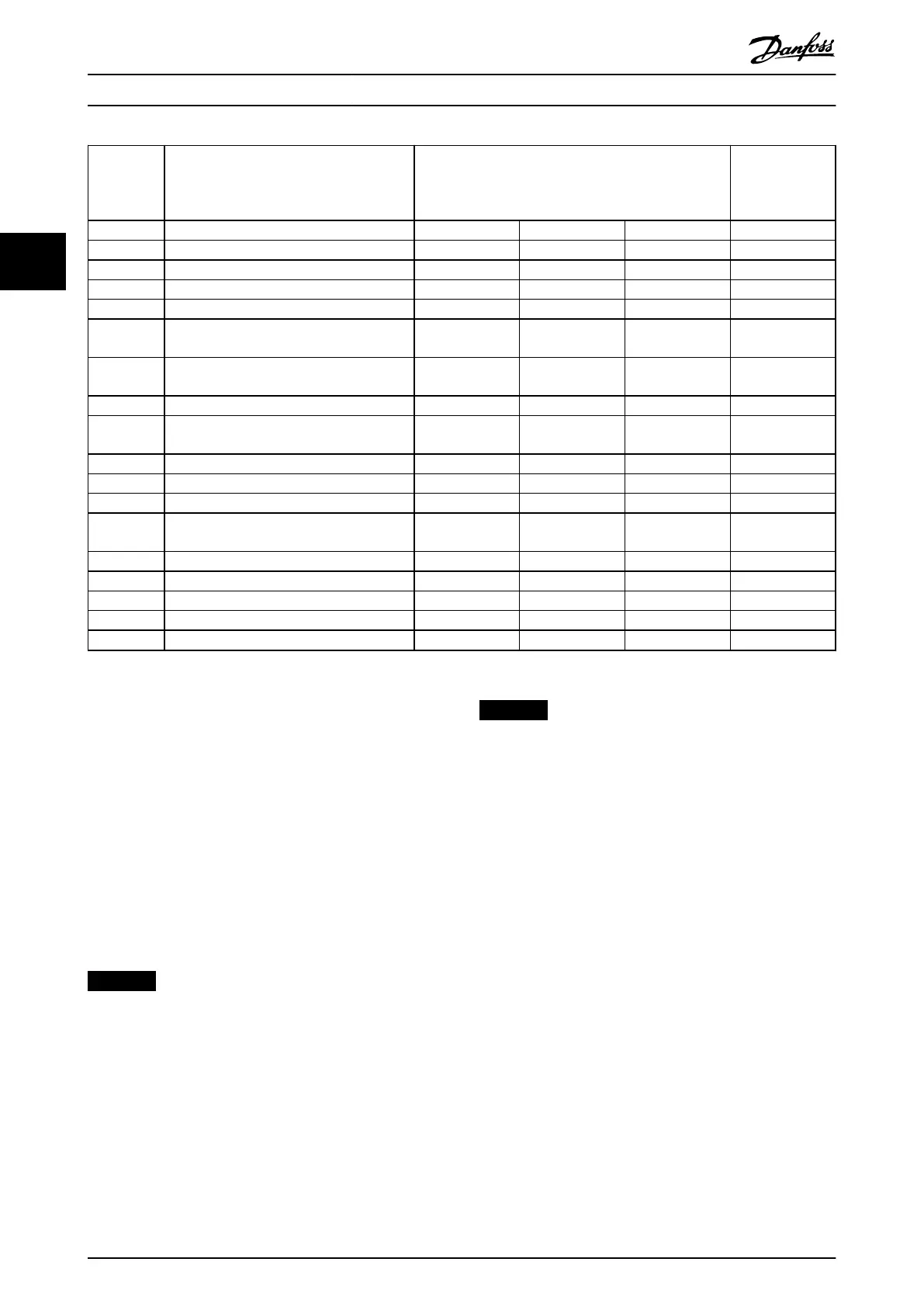
Alarm
Number
Description Fire mode alarm handling
selected in parameter 24-09 Fire Mode Alarm
Handling
Critical alarms causes a trip.
Warranty-
aecting alarms
in re mode
[0] Trip+Reset [1] Trip [2] Test
4 Mains phase loss ignored ignored (Warning / Trip) X
7 DC over voltage Trip+Reset Trip Warning / Trip
8 DC under voltage Trip+Reset Trip Warning / Trip
9 Inverter overloaded ignored ignored (Warning / Trip) X
13 Over Current Trip+Reset Trip
(Warning / Trip /
Trip lock)
14 Ground fault Trip+Reset Trip
(Warning / Trip /
Trip lock)
16 Short Circuit Trip+Reset Trip (Trip /Trip lock)
29 Heat sink temp ignored ignored
(Warning / Trip /
Trip lock)
X
33 Inrush fault ignored ignored Trip / Trip lock X
38 Internal fault ignored ignored Trip / Trip lock X
39 Heatsink sensor ignored ignored (Trip / Trip lock) X
65 Control Board Over temperature ignored ignored
Warning / Trip /
(Trip lock)
X
68 Safe Stop Trip Trip Trip
69 Pwr. Card Temp ignored ignored Trip / (Trip lock) X
244 Heatsink temp ignored ignored (Trip / Trip lock) X
245 Heatsink sensor ignored ignored (Trip / Trip lock) X
247 Pwr.card temp ignored ignored (Trip / Trip lock) X
Table 3.30 Fire Mode Alarm Handling
3.22.2 24-1* Drive Bypass
The frequency converter includes a feature, which can be
used to automatically activate an external electro-
mechanical bypass in case of a trip/trip lock of the
frequency converter or the event of a re mode coast (see
parameter 24-00 Fire Mode Function).
The bypass switches the motor to operation direct on line.
The external bypass is activated by 1 of the digital outputs
or relays in the frequency converter, when programmed in
parameter group 5-3* Digital Outputs or parameter group
5-4* Relays.
NOTICE
After enabling the drive bypass function, the frequency
converter is no longer safety certied (for using the safe
Torque O in versions, where included).
To deactivate the drive bypass at normal operation (re
mode not activated), carry out 1 of following actions:
•
Press [O] on the LCP, (or program 2 of the digital
inputs for Hand On-O-Auto).
•
Activate external interlock via digital input
•
Carry out a power cycling.
NOTICE
The drive bypass cannot be deactivated if in re mode. It
can be deactivated only by either removing the re
mode command signal or the power supply to the
frequency converter.
When the drive bypass function is activated, the display on
the LCP shows the status message Drive Bypass. This
message has a higher priority than the re mode status
messages. When the automatic drive bypass function is
enabled, it cuts in the external bypass according to the
sequence in Illustration 3.72
Parameter Descriptions
VLT
®
HVAC Drive FC 102
232 Danfoss A/S © 10/2019 All rights reserved. M0010001
33
 Loading...


