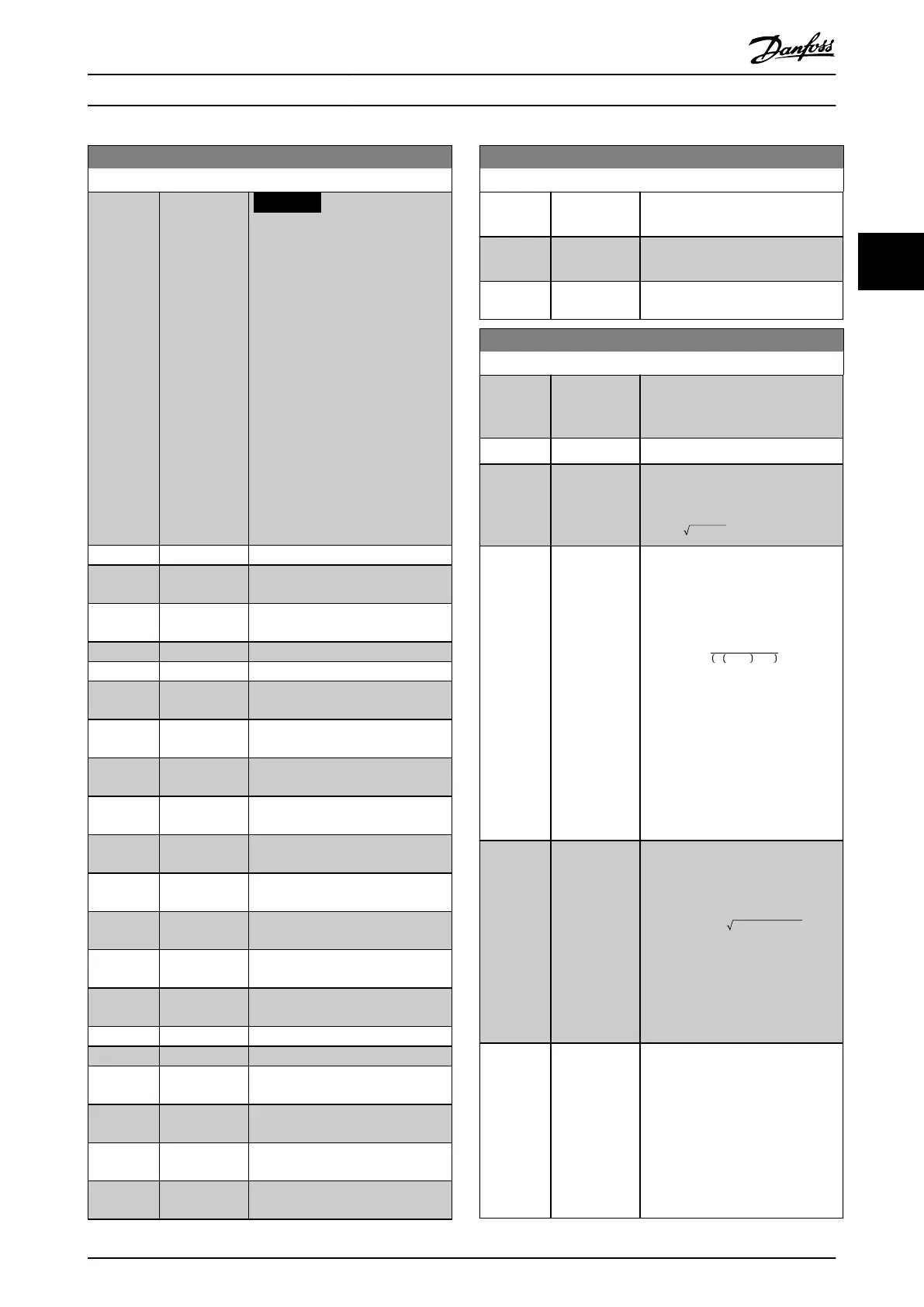
20-00 Feedback 1 Source
Option: Function:
NOTICE
If feedback is not used, set its
source to [0] No Function.
Parameter 20-20 Feedback
Function determines how the
PID controller uses the 3
possible feedbacks.
Up to 3 dierent feedback signals
can be used to provide the
feedback signal for the frequency
converter’s PID controller.
This parameter denes which input
is used as the source of the rst
feedback signal.
Analog input X30/11 and analog
input X30/12 refer to inputs on
VLT
®
General Purpose I/O MCB 101.
[0] No function
[1] Analog Input
53
[2] * Analog Input
54
[3] Pulse input 29
[4] Pulse input 33
[7] Analog Input
X30/11
[8] Analog Input
X30/12
[9] Analog Input
X42/1
[10] Analog Input
X42/3
[11] Analog Input
X42/5
[15] Analog Input
X48/2
[16] Analog Input
X49/1
[17] Analog Input
X49/3
[18] Analog Input
X49/5
[19] Pressure 3
[20] Pressure 4
[99] Normal
Feedback
[100] Bus Feedback
1
[101] Bus Feedback
2
[102] Bus feedback
3
20-01 Feedback 1 Conversion
Option: Function:
This parameter allows a conversion
function to be applied to feedback
1.
[0] * Linear No eect on the feedback.
[1] Square root Commonly used when a pressure
sensor is used to provide ow
feedback
(( flow ∝ pressure)).
[2] Pressure to
temperature
Used in compressor applications to
provide temperature feedback using
a pressure sensor. The temperature
of the refrigerant is calculated using
the following formula:
Temperature =
A2
ln Pe + 1 − A1
− A3,
where A1, A2, and A3 are
refrigerant-specic constants. Select
the refrigerant in
parameter 20-30 Refrigerant.
Parameter 20-21 Setpoint 1 through
parameter 20-23 Setpoint 3 allow the
values of A1, A2, and A3 to be
entered for a refrigerant that is not
listed in parameter 20-30 Refrigerant.
[3] Pressure to
ow
Used in applications for controlling
the air ow in a duct. A dynamic
pressure measurement (pitot tube)
represents the feedback signal.
Flow = DuctArea × DynamicPressure
× AirDensityFactor
See also parameter 20-34 Duct 1
Area [m2] through
parameter 20-38 Air Density Factor
[%] for setting of duct area and air
density.
[4] Velocity to
ow
Used in applications for controlling
the air ow in a duct. An air
velocity measurement represents
the feedback signal.
Flow = DuctArea × AirVelocity
See also parameter 20-34 Duct 1
Area [m2] through
parameter 20-37 Duct 2 Area [in2]
for setting of duct area.
 Loading...


