TROUBLESHOOTING
PRODUCT REFERENCE GUIDE
303
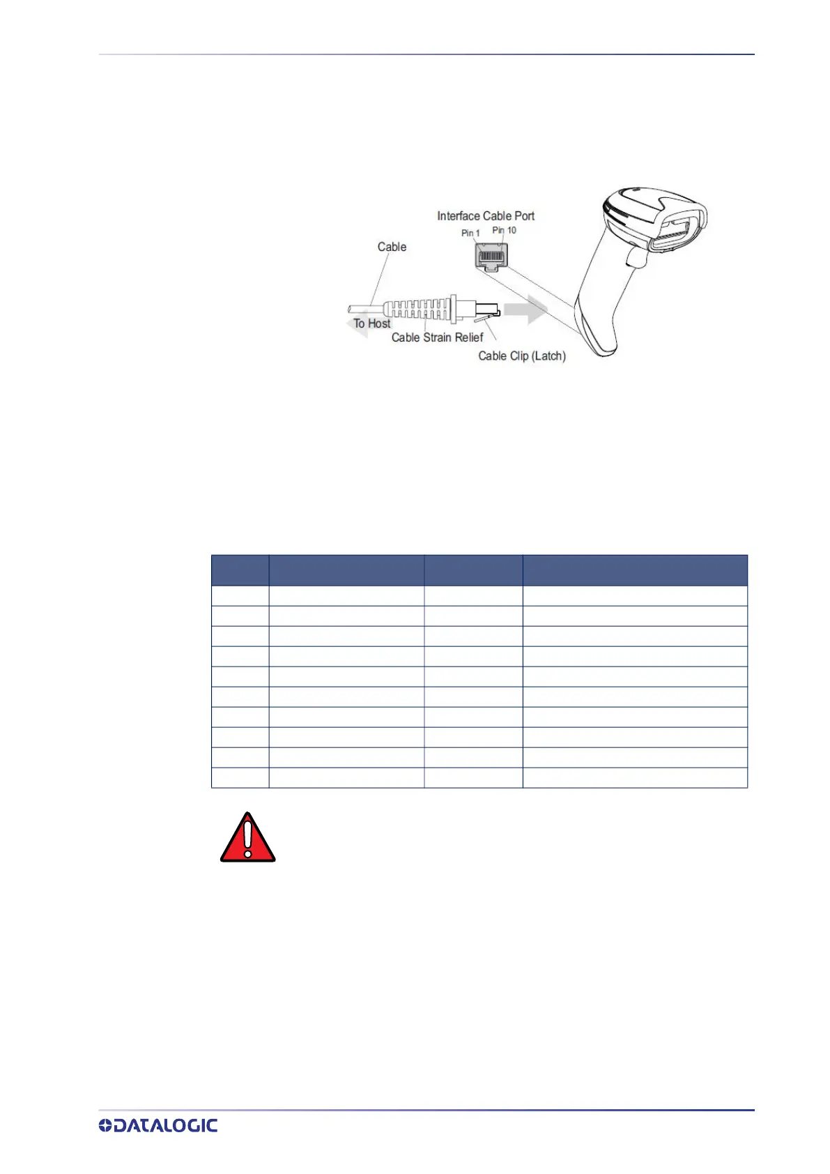
Figure 21 and Table 35 provide standard pinout information for the reader’s cable.
Figure 21 Standard Cable Pinouts
The signal descriptions in Table 35 apply to the connector on the reader and are for ref-
erence only.
Table 35 Standard Cable Pinouts — Reader Side
PIN RS232 USB KEYBOARD WEDGE
1 RTS (out)
2 D+ CLKIN (KBD side)
3 D- DATAIN (KBD side)
4 GND GND GND
5 RX
6 TX
7 VCC VCC VCC
8 CLKOUT (PC side)
9 DATAOUT (PC side)
10 CTS (in)
WARNING: Only official Datalogic cables are allowed for installation and
use. Non-standard P/N or wrong cable connection may lead to scanner
and/or host port permanent damage.
Please refer to Datalogic Technical Support to get information about the
cable's P/N most suitable for your application.
 Loading...