3. Disconnect the LED-board cable from the connector on the system board.
4. Peel the LED-board cable from the computer.
5. Remove the single screw (M2x3) that secures the LED board to the palm-rest assembly.
6. Lift the LED board and cable away from the palm-rest assembly.
Installing the LED board
Prerequisites
If you are replacing a component, remove the existing component before performing the installation procedure.
About this task
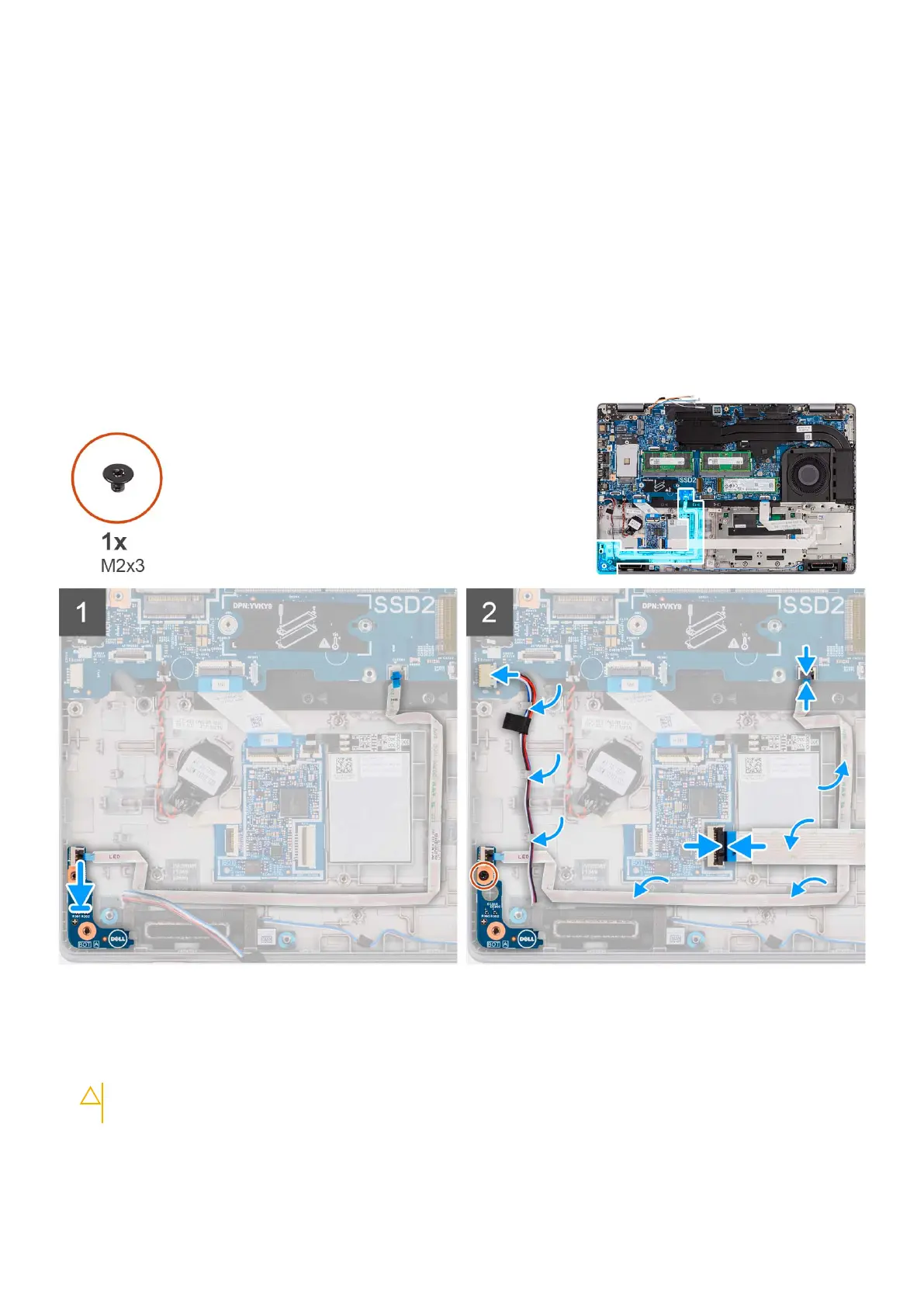
The following images indicate the location of the LED board and provide a visual representation of the installation procedure.
Steps
1. Align the screw hole on the LED board with the screw hole on the palm-rest assembly.
2. Replace the single screw (M2x3) to secure the LED board to the palm-rest assembly.
3. Route the LED-board cable and connect the cable to the connector on the system board.
CAUTION:
Do not route the LED-board cable under the coin-cell battery. Incorrect routing of the LED-board
cable may damage the LED board, LED-board cable, and system board.
4. Route the smartcard reader cable on the palm-rest assembly.
5. Connect the smartcard reader cable to the connector on the USH-daughter board and close the latch.
60
Removing and installing components
 Loading...