2. Align the captive screws on the heat sink to the screw holes on the system board.
3. In sequential order (1>2>3>4>5>6>7), tighten the seven captive screws that secure the heat sink to the system board.
4. Connect the display-assembly cable to its connector (LCD1) on the system board and close the latch.
5. Adhere the tape to secure the display-cable latch to its connector (LCD1) to the system board.
6. Place the front-firing speaker cable into its routing guides.
7. Connect the front-firing speaker cable to its connector (SPK2) on the system board.
Next steps
1. Install the base cover.
2. Follow the procedure in After working inside your computer.
I/O board
Removing the I/O board
CAUTION: The information in this section is intended for authorized service technicians only.
Prerequisites
1. Follow the procedure in Before working inside your computer.
NOTE:
Ensure that your computer is in Service Mode. For more information, see step 6 in Before working inside your
computer.
2. Remove the base cover.
3. Remove the graphics processing unit fan.
4. Remove the heat sink.
About this task
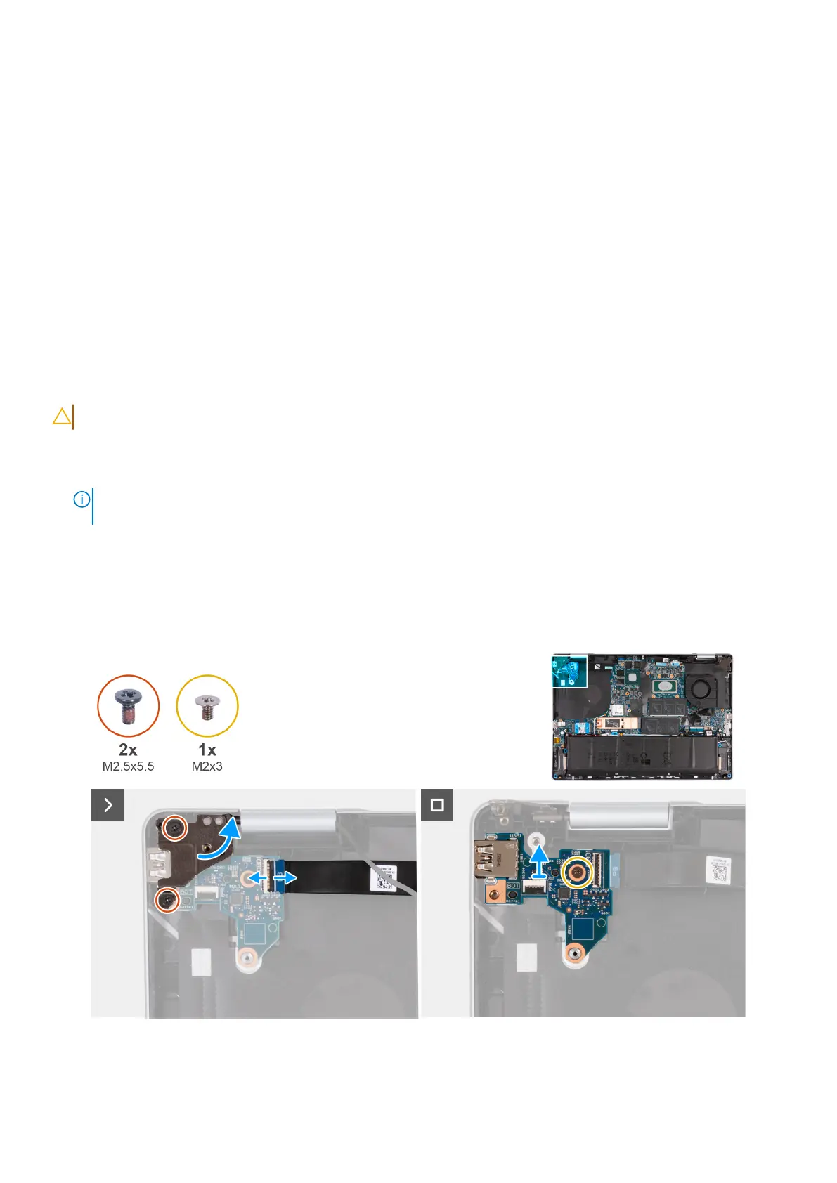
The following image(s) indicate the location of the I/O board and provides a visual representation of the removal procedure.
Figure 44. Removing the I/O board
Removing and installing Field Replaceable Units (FRUs)
69
 Loading...