About this task
The following image(s) indicate the location of the power-adapter port and provides a visual representation of the removal
procedure.
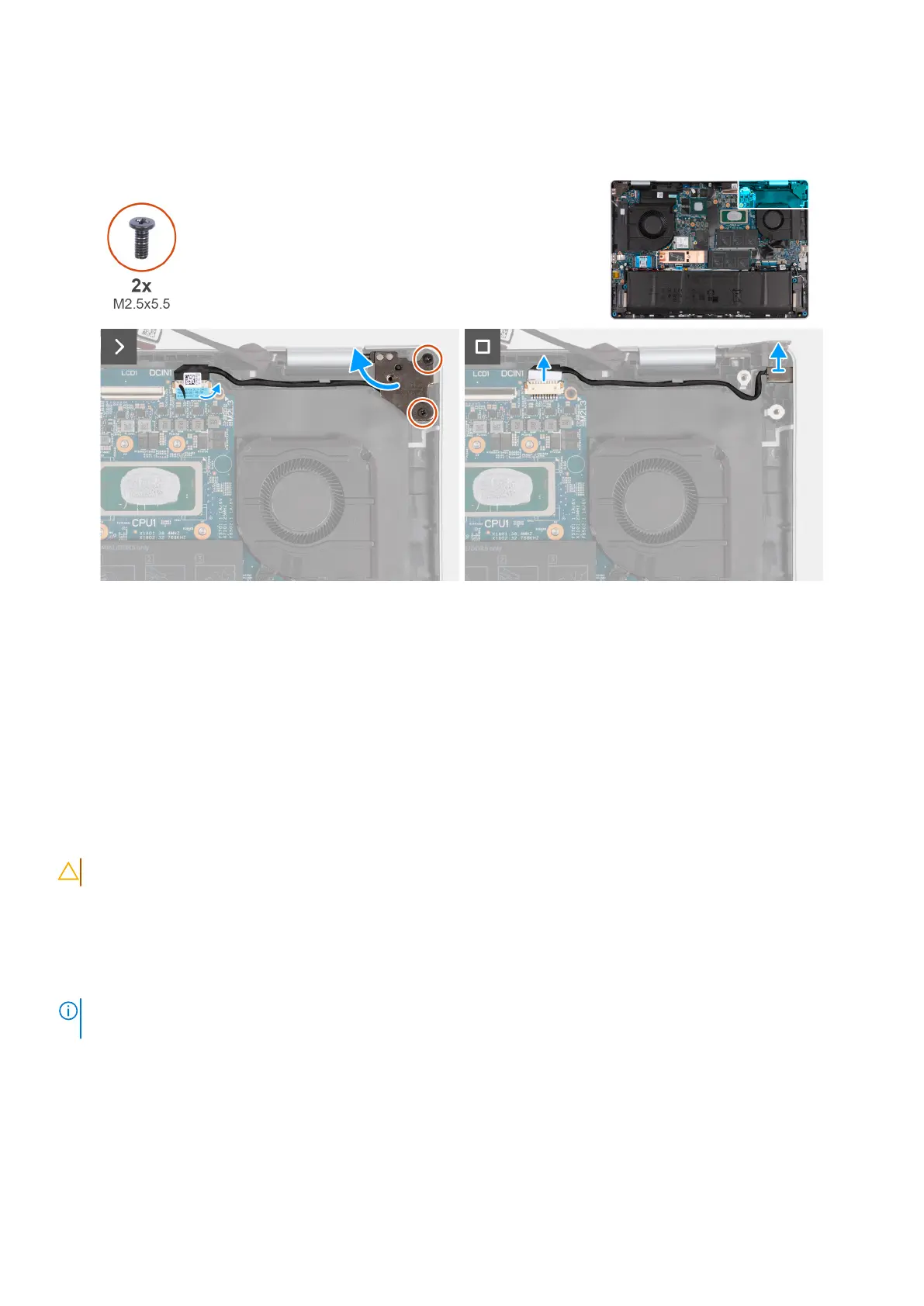
Figure 52. Removing the power-adapter port
Steps
1. Remove the two screws (M2.5x5.5) that secure the right-display assembly hinge to the system board.
2. Pry open the right-display assembly hinge at an angle of 90 degrees.
3. Peel off the tape that secures the power-adapter port cable to its connector (DCIN1) on the system board.
4. Disconnect the power-adapter port cable from its connector (DCIN1) on the system board.
5. Remove the power-adapter port cable from the routing guide on the palm-rest and keyboard assembly.
6. Lift the power-adapter port off the palm-rest and keyboard assembly.
Installing the power-adapter port
CAUTION: The information in this section is intended for authorized service technicians only.
Prerequisites
If you are replacing a component, remove the existing component before performing the installation process.
About this task
NOTE:
If either the system board or the heat sink is replaced, use the thermal grease that is provided in the kit to ensure
that thermal conductivity is achieved.
The following image(s) indicate the location of the power-adapter port and provides a visual representation of the installation
procedure.
Removing and installing Field Replaceable Units (FRUs)
77
 Loading...