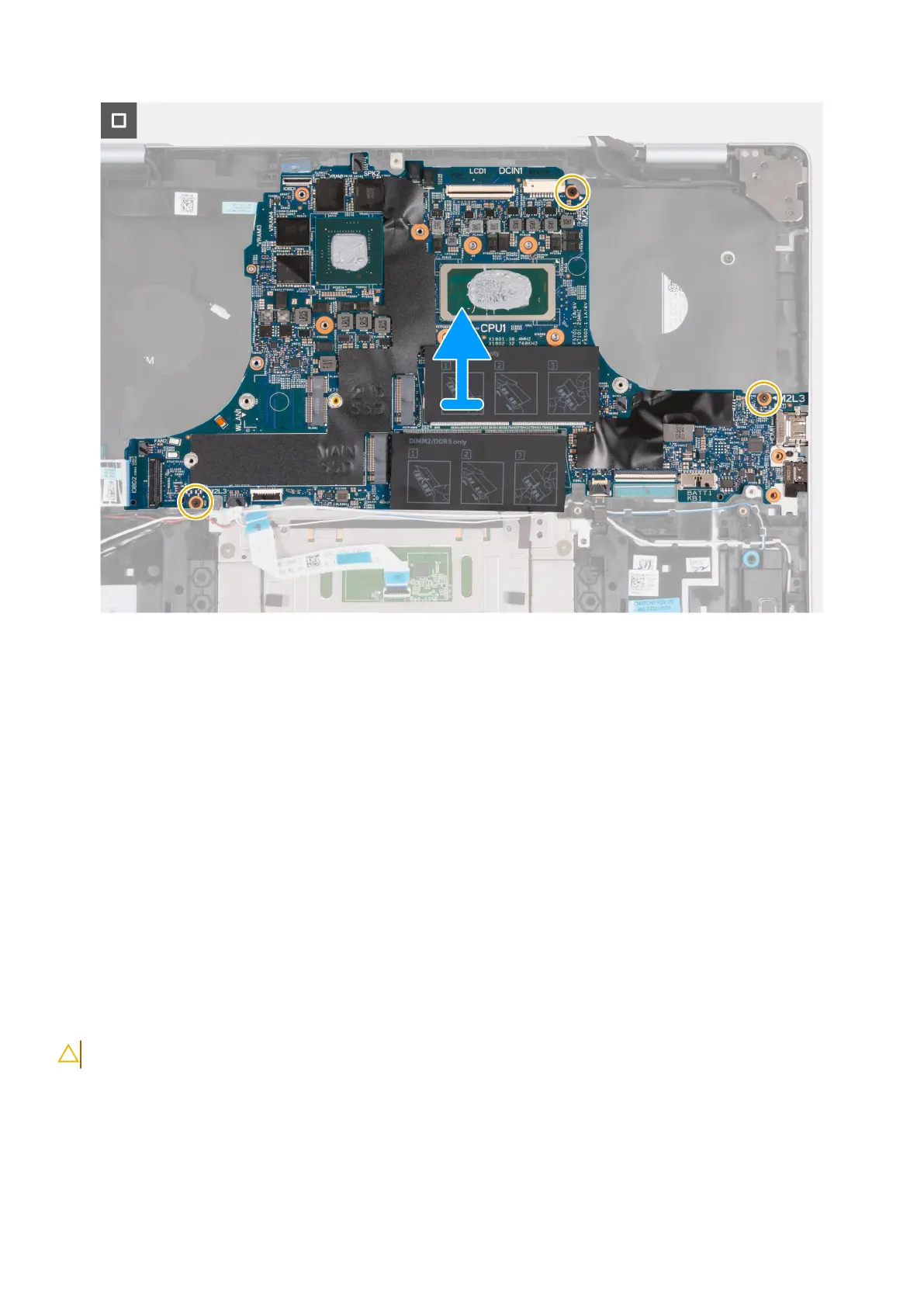
Figure 56. Removing the system board
Steps
1. Lift the latch and disconnect the I/O-board cable from its connector (IOBD1) on the system board.
2. Peel off the tape that secures the power-adapter port cable to its connector (DCIN1) on the system board.
3. Disconnect the power-adapter port cable from its connector (DCIN1) on the system board.
4. Remove the two screws (M2x4) that secure the Type-C bracket to the system board.
5. Lift the Type-C port bracket off the system board.
6. Lift the latch and disconnect the keyboard cable from its connector (KB1) on the system board.
7. Lift the latch and disconnect the keyboard-backlight cable from its connector (KBBL1) on the system board.
8. Lift the latch and disconnect the touchpad cable from its connector (TP1) on the system board.
9. Disconnect the down-firing speaker cables from their connector (SPK1) on the system board.
10. Remove the antenna cables from their routing guides on the system board.
11. Lift the latch and disconnect the audio-board cable from its connector (IOBD2) on the system board.
12. Remove the three screws (M2x3) that secure the system board to the palm-rest and keyboard assembly.
13. Lift the system board off the palm-rest and keyboard assembly.
Installing the system board
CAUTION: The information in this section is intended for authorized service technicians only.
Prerequisites
If you are replacing a component, remove the existing component before performing the installation process.
Removing and installing Field Replaceable Units (FRUs)
81
 Loading...