1. PLC Concepts
1.2 Current Flow
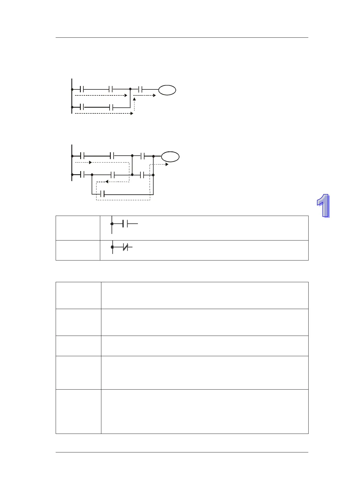
Ladder logic follows a left to right principle. In the example below, the current flows through paths
started from either X0 or X3.
Reverse Current
When a current flows from right to left, which makes a reverse current logic, an error will be
detected when compiling the program. The example below shows the reverse current flow.
1.3 NO Contact, NC Contact
Normally Open Contact, A contact
Normally Closed Contact, B contact
1.4 PLC Registers and Relays
Introduction to the basic internal devices in a PLC
X
(Input Relay)
Bit memory represents the physical input points and receives external input
signals.
Device indication: Indicated as X and numbered in octal, e.g. X0~X7,
Y
(Output Relay)
Bit memory represents the physical output points and saves the status to be
refreshed to physical output devices.
Device indication: Indicated as Y and numbered in octal, e.g. Y0~Y7,
M
(Internal Relay)
Bit memory indicates PLC status.
Device indication: Indicated as M and numbered in decimal, e.g. M0, M1,
S
(Step Relay)
Bit memory indicates PLC status in Step Function Control (SFC) mode. If no
STL instruction is applied in program, step point S can be used as an internal
relay M as well as an annunciator.
Device indication: Indicated as S and numbered in decimal, e.g. S0, S1,
T
(Relay)
(Word)
(Dword)
Bit, word or double word memory used for timing and has coil, contact and
register in it. When its coil is ON and the set time is reached, the associated
contact will be energized. Every timer has its resolution (unit:
1ms/10ms/100ms).
Device indication: Indicated as T and numbered in decimal, e.g. T0, T1,
T2…T255

 Loading...


