5. Sequential Function Chart
5.6 IST Instruction
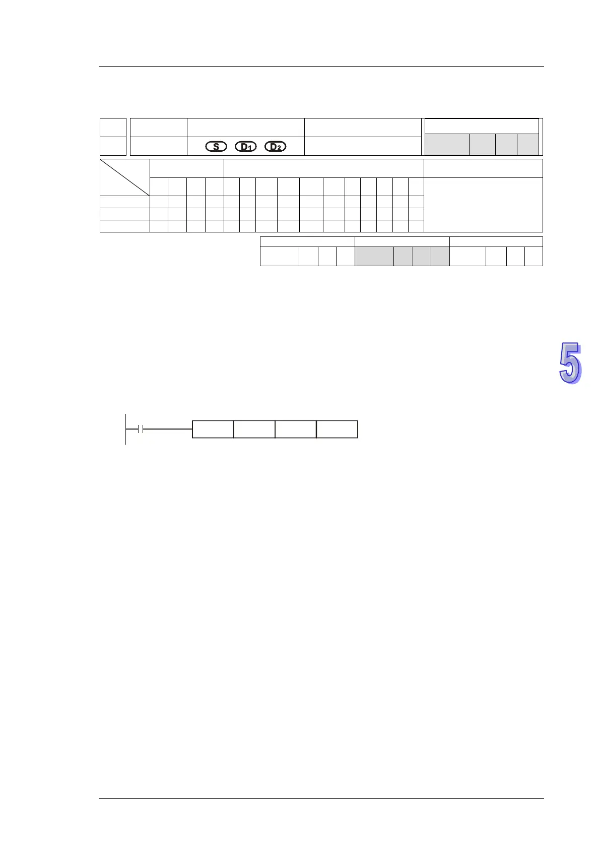
API
Mnemonic Operands Function
60 IST
Initial State
Type
OP
Bit Devices Word devices Program Steps
X Y M S K H KnX
KnY
KnM
KnS
T C D E F
IST: 7 steps
SS2
SA2
SX2
SS2
SA2
SX2
SS2
SA2
SX2
Operands:
S: Source device for assigning pre-defined operation modes (8 consecutive devices). D
1
The
smallest No. of step points in auto mode. D
2
: The greatest No. of step points in auto mode.
Explanations:
1. The IST is a handy instruction specifically for the initial state of the step ladder operation modes.
2. The range of D
1
and
D
2
: S20~S911, D
1
< D
2
.
3. IST instruction can only be used one time in a program.
Program Example 1:
1. Operation mode:
S:
X20: Individual operation (Manual operation)
X21: Zero return
X22: Step operation
X23: One cycle operation
X24: Continuous operation
X25: Zero return start switch
X26: Start switch
X27: Stop switch
2. When IST instruction is executed, the following special auxiliary relays will be assigned
automatically.
M1040: Movement inhibited
M1041: Movement start
M1042: Status pulse
M1047: STL monitor enable
S0: Manual operation/initial state step point
S1: Zero point return/initial state step point
S2: Auto operation/initial state step point
3. When IST instruction is used, S10~S19 are occupied for zero point return operation and cannot
be used as a general step point. In addition, when S0~S9 are in use, S0 initiates “manual
operation mode”, S1 initiates “zero return mode” and S2 initiates “auto mode”. Thus, the three
step points of initial state have to be programmed in first priority.
4. When S1 (zero return mode) is initialized, i.e. selected, zero return will NOT be executed if any
of the state S10~S19 is ON.

 Loading...


