Appedndix B Setting and Using an Ethernet PLC/Module
B-21
B.6 RTU Mapping
Users can connect the Delta network product DVPEN01-SL/DVP-SE/ES2-E to RTU-EN01 by
means of RTU mapping. After the users finish setting mapping information, they can operate
RTU-EN01 by means of corresponding bits (M devices) and registers (D devices) in
DVPEN01-SL/DVP-SE/ES2-E instead of communication programs.
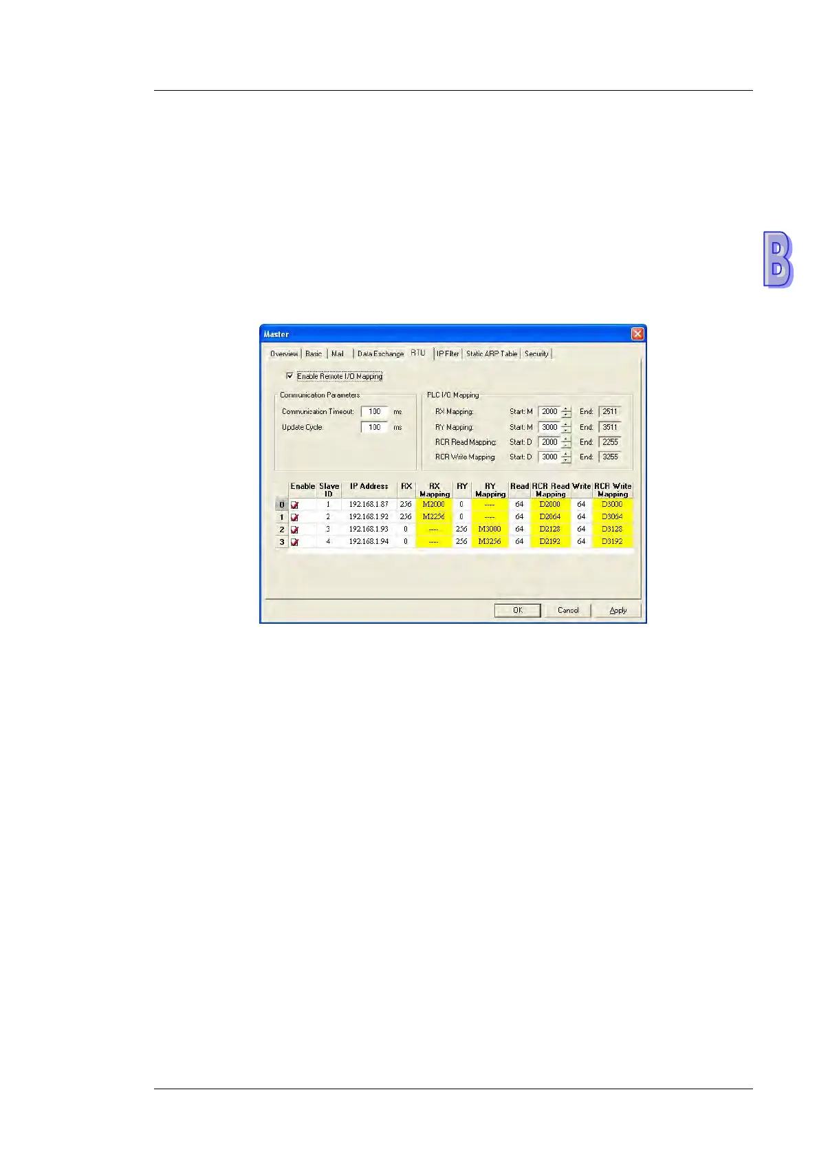
B.6.1 Setting the RTU Mapping
(1) Enable Remote I/O Mapping
Users can select the Enable Remote I/O Mapping checkbox. After the checkbox is selected,
the network module used will be mapped onto RTU-EN01 according to the data set.
(2) Communication Parameters
Users can enter a time interval in the Communication Timeout box, and a cycle in the
Update Cycle box.
(3) PLC I/O Mapping
Users can set the bit devices and the registers which correspond to digital inputs, digital
outputs, and analog registers on RTU-EN01. The bit devices set start from M2000. The
registers used for the reading of data start from D2000, and the registers used for the writing
of data start from D3000. The software automatically calculates end addresses according to
the numbers set.
(4) Setting the remote device mapping
After users check an Enable cell, they have to enter the station address of RTU-EN01, an IP
address, the number of digital inputs, the number of digital outputs, the number of registers
used for the reading of data, and the number of registers used for the writing of data.
DVPEN01-SL can be mapped onto four slaves. The maximum number of digital inputs used

 Loading...


