4. Communications
4.3 Communication Protocol RTU mode
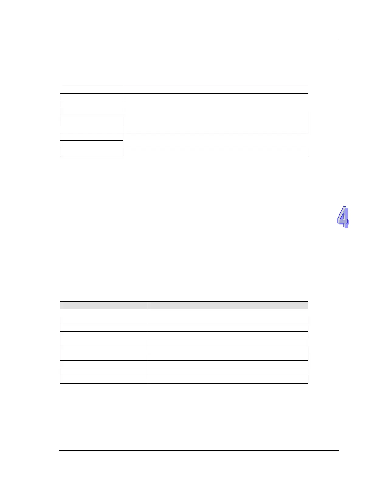
Communication Data Structure
9600
(Baud rate), 8 (data bits), EVEN (Parity), 1 (Start bit), 1 (Stop bit)
≥
Communication Address: the 8-bit binary address
Command Code: the 8-bit binary address
Data Contents:
n × 8-bit BIN data, n≦202
…….
CRC Checksum:
The 16-bit CRC checksum is composed of 2 8-bit binary codes
≥
4.3.1 Address (Communication Address)
Valid communication addresses are in the range of 0~254. Communication address equals to 0 means
broadcast to all PLCs. PLC will not respond to a broadcast message. PLC will reply a normal message
to the master device when communication address is not 0.
Example, communication address should be set to 10 (Hex) when communicating with a PLC with
address 16 (Dec) (16 in Decimal = 10 in Hex)
4.3.2 CMD (Command code) and DATA
The content of access data depends on the command code. For descriptions of available command
codes, please refer to 4.2.2 in this chapter.
Example: read consecutive 8 words from address 0614H~H61B (T20~T27) of PLC Slave ID#1.
PC→PLC
“ 01 03 06 14 00 08 04 80”
Sent message:
≥
Starting Address
Number of Points
≥

 Loading...


