DVP-ES2/EX2/EC5/SS2/SA2/SX2/SE&TP Operation Manual - Programming
C
(Counter)
(Relay)
(Word)
(Dword)
Bit, word or double word memory used for counting and has coil, contact and
register in it. The counter count once (1 pulse) when the coil goes from OFF to
ON. When the predefined counter value is reached, the associated contact will
be energized. There are 16-bit and 32-bit high-speed counters available for
users.
Device indication: Indicated as C and numbered in decimal, e.g.
D
(Data register)
(Word)
Word memory stores values and parameters for data operations. Every
register is able to store a word (16-bit binary value). A double word will occupy
2 consecutive data registers.
Device indication: Indicated as D and numbered in decimal, e.g. D0, D1,
E, F
(Index register)
(Word)
Word memory used as a modifier to indicate a specified device (word and
double word) by defining an offset. Index registers not used as a modifier can
be used as general purpose register.
Device indication: indicated as E0 ~ E7 and F0 ~ F7.
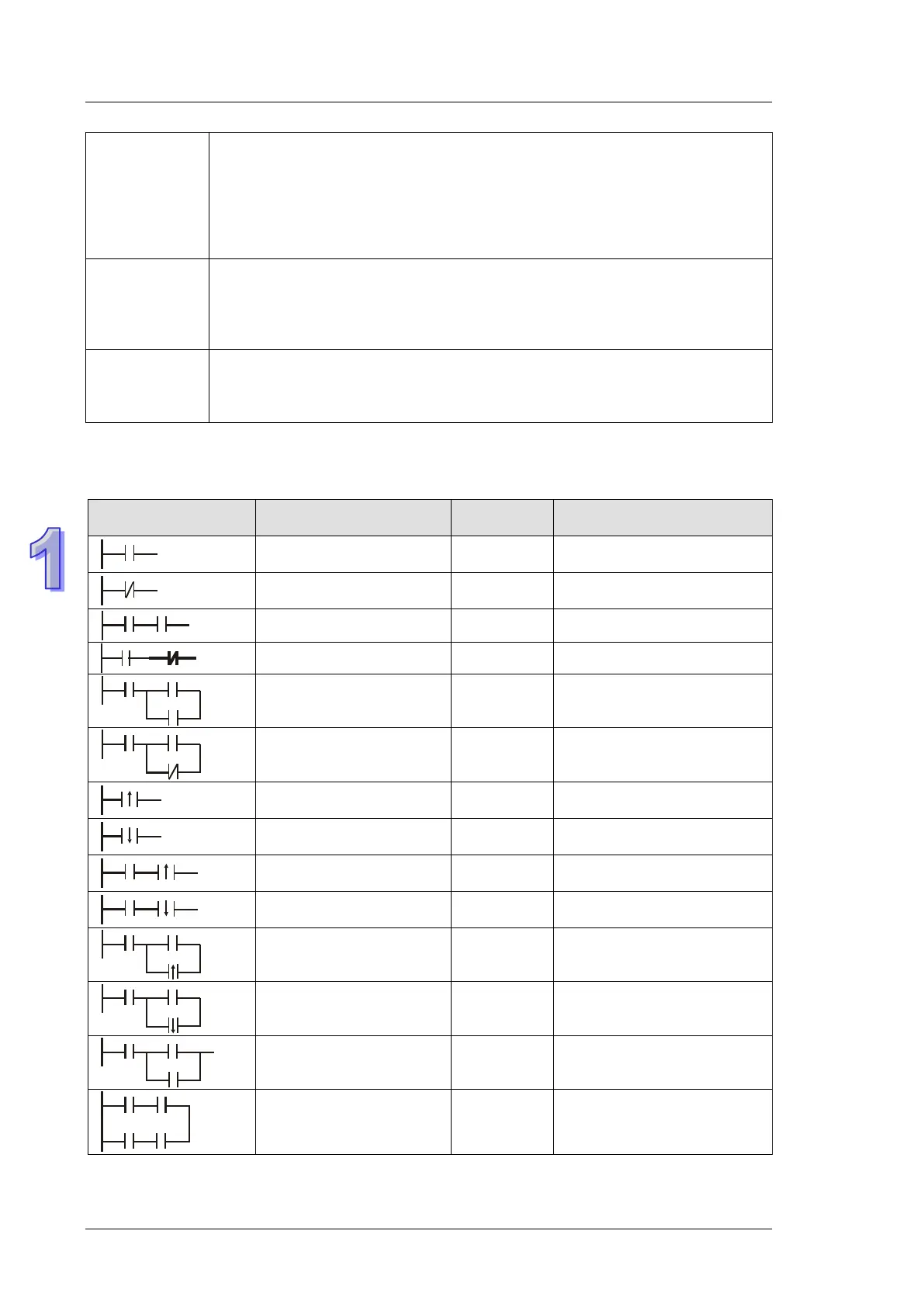
1.5 Ladder Logic Symbols
The following table displays list of WPLSoft symbols their description, command, and memory
registers that are able to use the symbol.
Explanation Instruction Available Devices
NO (Normally Open)
contact / A contact
LD X, Y, M, S, T, C
NC (Normally Closed)
contact / B contact
LDI X, Y, M, S, T, C
NO contact in series AND X, Y, M, S, T, C
NC contact in series ANI X, Y, M, S, T, C
NO contact in parallel OR X, Y, M, S, T, C
NC contact in parallel ORI X, Y, M, S, T, C
Rising-edge trigger
switch
LDP X, Y, M, S, T, C
Falling-edge trigger
switch
LDF X, Y, M, S, T, C
Rising-edge trigger in
series
ANDP X, Y, M, S, T, C
Falling-edge trigger in
series
ANDF X, Y, M, S, T, C
Rising-edge trigger in
parallel
ORP X, Y, M, S, T, C
Falling-edge trigger in
parallel
ORF X, Y, M, S, T, C
Block in series ANB None
Block in parallel ORB None

 Loading...


