DVP-ES2/EX2/EC5/SS2/SA2/SX2/SE&TP Operation Manual - Programming
Editing the Ladder Diagram through WPLsoft
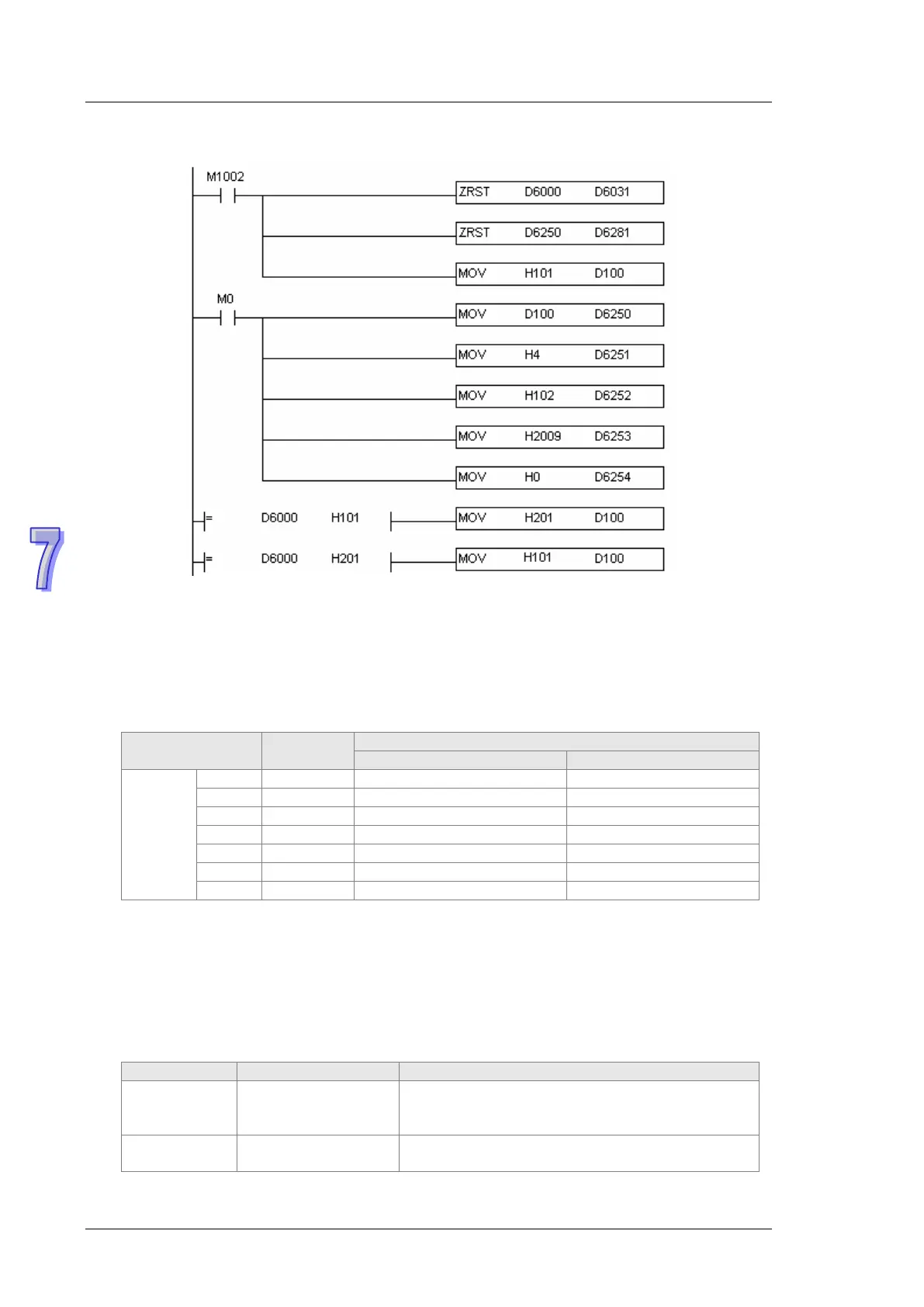
When M0=ON, DVP-ES2-C sends out the first request message and D6000 should be
101(hex) after the response message is transmitted back successfully. In program, if the
value of D6000 is judged as 101(hex), the ReqID is changed into 2 and D6250 is given a new
value 201(hex) and DVP-ES2-C sends out the request message again. By dong so, the
real-time reading can be realized. After reading succeeds, the data returning from the target
device are stored in D6000~D6005. The value of D6005: 100(hex)is the read value of P0-09.
Explanation of Response Message Devices:
7.5 Indicators and Troubleshooting
There are 6 LED indicators on DVP-ES2-C. Power indicator shows whether the power is normal,
RUN and ERROR indicator display the state of running of internal program and COM3 displays the
communication state of CANopen.
7.5.1 Description of Indicators
POWER indicator
the green light
The supply power is
abnormal
Check if the supply power is in the valid range
The supply power is
normal
No resolution is required
PLC device
SDO
response
message
mapping
area
Main index high byte = 20

 Loading...


