DVP-ES2/EX2/EC5/SS2/SA2/SX2/SE&TP Operation Manual - Programming
D
Content
EX2
SS2
SA2
SE
SX2
Attrib.
Latch
-ed
Default
(It is only applicable to DVP-ES2-C series
MPUs. If DVP-ES2-C V3.24 (or above) is
turned from OFF to ON, the value in
D9998 will be H’0. If DVP-ES2-C V3.26 (or
above) is turned from OFF to ON, the
value in D9998 will be H’FFFF.)
D9999
Showing the CAN baud rate
K1: 20K; K2: 50K; K3: 125K; K4: 250K; K5:
500K; K6: 1M
(It is only applicable to DVP-ES2-C V3.26
ES2-C:
V3.26
╳ ╳ ╳
0 - - R NO 0
2.14 E, F Index Registers
Index registers are used as modifiers to indicate a specified device (word, double word) by defining
an offset. Devices can be modified includes byte device (KnX, KnY, KnM, KnS, T, C, D) and bit
device (X, Y, M, S). E, F registers cannot be used for modifying constant (K, H) Index registers not
used as a modifier can be used as general purpose register.
Index register [E], [F]
Index registers are 16-bit registers which can be read and written. There are 16 points indicated as
E0~E7 and F0~F7. If you need a 32-bit register, you have to designate E. In this case, F will be
covered up by E and cannot be used. It is recommended to use instruction DMOVP K0 E to reset E
(including F) at power-on.
F0
E0
E0
F0
16-bit
16-bit
32-bit
Low word
High word
The combinations of E and F when designating a 32-bit register are:
(E0, F0) , (E1, F1) (E2, F2) (E3, F3) (E4, F4) , (E5, F5) (E6, F6) (E7, F7)
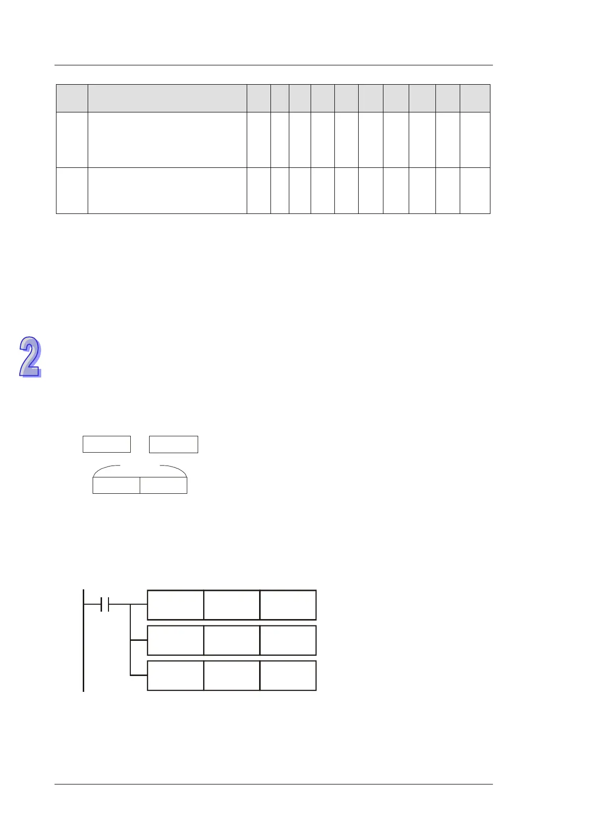
Example:
When X0 = ON and E0 = 8, F0 = 14, D5E0 = D(5+8) = D13, D10F0 = D(10+14) = D24, the content
in D13 will be moved to D24.
K14 F0
X0
K8 E0MOV
D5E0 D10F0
MOV
MOV
 Loading...


