7 CANopen Function and Operation
F5
DVP-ES2-C setting error such
as incorrect node address
The node address of DVP-ES2-C should be
set in the range: 1~127.
F8
Internal error; the error is
detected in the internal memory
After re-powering, change into a new one if
the error still exists.
FB
The sending buffer in
DVP-ES2-C is full.
Check if the CANopen bus cable is properly
connected and then re-power.
FC
The receiving buffer in
DVP-ES2-C is full.
Check if the CANopen bus cable is properly
connected and then re-power.
Code display in D9980 as DVP32ES2-C is in slave mode:
DVP-ES2-C is being initialized.
A1 DVP-ES2-C is pre-operational.
Check if the CANopen bus cable is properly
connected
A3
The data are being downloaded
to DVP-ES2-C
Wait to finish downloading the configured
data.
B0 Heartbeat message is timed-out
Check if the CANopen bus cable is properly
connected.
B1
PDO data length returned from
the slave is not consistent with
the length set in the node list.
Reset the PDO data length in the slave and
download the new setting to DVPCOPM-SL.
F4 BUS-OFF state is detected.
Check if CANopen bus cables are properly
connected and ensure that all the node
devices run at the same baud rate before
FB
The sending buffer in
DVP-ES2-C is full.
Check if the CANopen bus cable is properly
connected and then re-power.
FC
The receiving buffer in
DVP-ES2-C is full.
Check if the CANopen bus cable is properly
connected and then re-power.
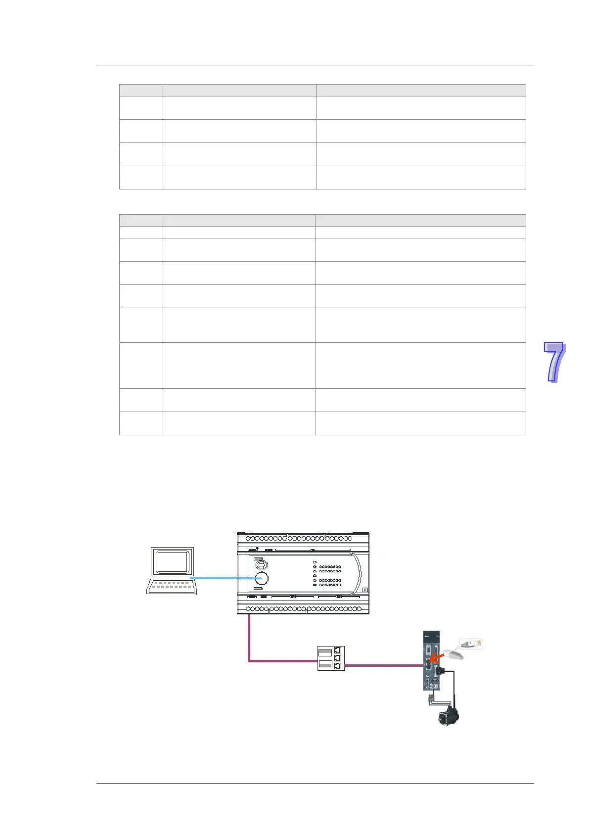
7.6 Application Example
DVP-ES2-C is used to control Delta A2 servo rotation and monitor the actual rotation speed of
motor in real time. The principle of operation is to map the relevant parameters of servo drive to the
corresponding PDO and read or write the relevant parameters of servo drive through the CAN bus
to accomplish the control requirement.
Hareware Connection:
DVP32ES2-C
PC
TAP-CN03
Y5UP0 Y0 Y1 Y3Y2 Y4 Y10Y7Y6 UP1 Y 12Y11 Y13
+24V
L N NC X5X1S/S24G X0 X3X2 X4 X11X7X6 X10 X13X12 X14 X15
Y16Y15Y14
Y17
X17X 16
ZP1ZP0CAN+ SG
+
D D
-
CAN-
ASDA-A2-xxxx-M
CANopen
CANopen
RS-232

 Loading...


