Appedndix B Setting and Using an Ethernet PLC/Module
B-3
B.2 Ethernet Control Registers
B.2.1 Station Addresses of Ethernet Modules
Model name
DVP-SE / ES2-E
DVPEN01-SL
(Applicable to a DVP-EH3
K108
Please refer to
Example 1.
K108
Example 1: A DVP-SV series MPU is connected to three left-side communication modules.
DVPEN01-SL DVPCOPM-SL DVPEN01-SL DVP28SV11R
K102 K101 K100 --
B.2.2 DVP-SE / ES2-E Series PLC (Ethernet PLC)
In order to control and monitor Ethernet communication, users can read the data in the control
registers listed below by means of the instruction FROM, and write data into the control registers
listed below by means of the instruction TO. (Please refer to the explanation of API 78 and that of
API 79 in chapter 3 for more information about FROM/TO.)
[Note] Please refer to DVPEN01-SL Manual for more information about control registers.
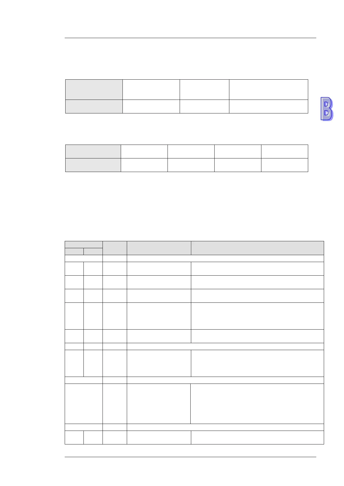
Attribute
Register name Description
#13 R/W
Enabling the data
exchange
Users can set CR#13 to “sending the data” or “not
sending the data”.
#14 R/W
Writing function of the
RTU mapping
0: The PLC writes data continually.
1: The PLC writes data when the input changes.
#15 R/W
Enabling flag for RTU
mapping
1: Enable; 0: Disable. Default = 1
#16 R/W
Connection status of
RTU mapping slave
b0: Status of RTU slave 1
b1: Status of RTU slave 2
b2: Status of RTU slave 3
b3: Status of RTU slave 4
#17 R/W
Execution cycle of the
data exchange
Time unit: ms
#19 R
States of the slaves
involved in the data
exchange
If the value of a bit is 1, an error occurs in the
slave corresponding to the bit.
b[0:7] indicate the states of the slaves 1~8
involved in the data exchange.
#27 R/W
Function code for a
data exchange mode
0: The function code for the reading of data and
the writing of data is “17”.
1: The function codes for the reading of data is
“03, the function code for the writing of a single
piece of data is “06”, and the function code for the
writing of multiple pieces of data is “10”.
#87 R/W

 Loading...


