1. PLC Concepts
Example 5:
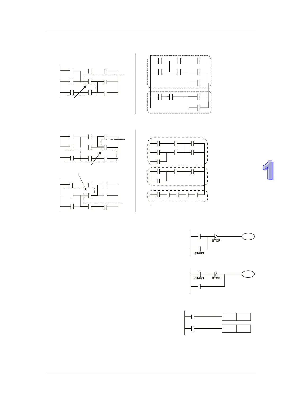
Correct the circuit of reverse current. The pointed reverse current loops are modified on the right.
X0
X3
X6
X1
X4
X7
X2
X5
X10
LOOP1
reverse current
Example 6:
Correct the circuit of reverse current. The pointed reverse current loops are modified on the right.
X0
X3
X6
X1
X4
X7
X2
X5
X1
0
LOOP1
reverse current
LOOP1
X0 X1 X2
X3 X4 X5
X6
X3 X7 X10
X6
X0 X1 X7
X10
LOOP
2
X4
X0
X3
X6
X1
X4
X7
X2
X5
X1
0
LOOP2
Reverse current
1.9 Basic Program Design Examples
Example 1 - Stop First latched circuit
When X1 (START) = ON and X2 (STOP) = OFF, Y1 will be ON.
If X2 is turned on, Y1 will be OFF. This is a Stop First circuit
because STOP button has the control priority than START
Example 2 - Start First latched circuit
When X1 (START) = ON and X2 (STOP) = OFF, Y1 will be ON
and latched. If X2 is turned ON, Y1 remains ON. This is a Start
First circuit because START button has the control priority than
STOP
Example 3 - Latched circuit of SET and RST
The diagram opposite are latched circuits consist of RST and
SET instructions.
In PLC processing principle, the instruction close to the end of
the program determines the final output status of Y1. Therefore,
if both X1 and X2 are ON, RST which is lower than SET forms a