Appedndix B Setting and Using an Ethernet PLC/Module
B-7
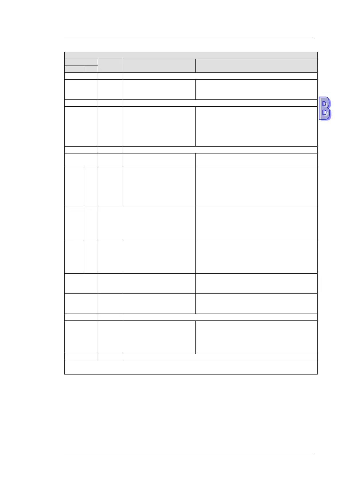
DVP-FEN01 Ethernet communication card
Attribute
Register name Description
#19 R
involved in the data
b[0:7] indicate the states of the slaves 1~8
involved in the data exchange.
#27 R/W
Function code for a data
exchange mode
0: The function code for the reading of data
and the writing of data is “17”.
1: The function code for the reading of data is
“03, the function code for the writing of a single
piece of data is “06”, and the function code for
the writing of multiple pieces of data is “10”.
#87 R/W IP address setting mode
#89 #88
R/W IP address
When the IP address is 192.168.1.5, the data
in CR#89 is 192.168, and the data
1.5. One CR takes two bytes, and the decimal
number should convert to hexadecimal one.
192 is H’C0, 168 is H’A8; type H’C0A8 in #89
#91 #90
R/W Mask address
When the mask address is 255.255.255.0 the
data in CR#91 is 255.255, and the data in
CR#90 is 255.0. One CR takes two bytes, and
the decimal number should convert to
#93 #92
R/W Gateway IP address
When the GIP address is 192.168.1.1, the
data in CR#89 is 192.168, and the data in
CR#88 is 1.1. One CR takes two bytes, and
the decimal number should convert to
#94 R/W
setting
0: The setting of the IP address is not
executed.
1: The setting of the IP address is executed.
#95 R IP address setting status
0: The setting is unfinished.
1: The setting is being executed.
2: The setting is complete.
#251 R Error status
bit 0: The network is unconnected.
bit 3: CR#13 is set to “sending the data”, but
the data exchange is not enabled.
bit 8: DHCP does not acquire the correct
Symbols “R” refers to “able to read data by FROM instrcution”; “W” refers to “able to write data by
TO instrcution”.

 Loading...


