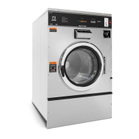
Outer Cabinet Removal
T-300, T350, T-400, T450, T-600
Removal of Cabinet T-300, T-350, T-400, T-450, T-600
Step 1: The power supply, water hoses, and drain connection must all be disconnected before proceeding
with the disassembly.
Step 2: Now remove the lower service panel and the top panel
assembly.
Step 3: Remove the left and right lower front panel screws that
retain the panel to the chassis.
Step 3: Remove the bottom row of back panel screws.
Step 4: Remove the loading door.
Step 5: Remove the screws along the bottom of each side panel.
When reinstalling these screws do not overtighten.
Step 6: Remove clamp and soap dispenser hose where it attaches
to the tub inlet. Disconnect the door lock wires from all
switches and the door lock solenoid.
Step 7: Disconnect pull rod between solenoid and door lock
assembly. Disconnect the wires to the dump valve at the
bottom of the machine.
Step 8: Disconnect the wires to the drive motor from the VFD T1,
T2, T3.
Step 9: Remove the clamp and the hose from the vacuum breaker
where it connects to the inlet on the back of the tub.
Step 10: Remove the pressure switch hose from the bottom of the
switch.
Step 11: It should now be possible for two people to lift the cabinet up and off of the front of the machine and
set it aside.
Door Locking Gear Motor Assembly
The door locking gear motor is rotated shut with
control voltage to lock the door and releases when
voltage is removed. It is located in the left front
corner of the washer. (Original l ocking solenoid
models can be converted to the new assembly)
Thermoactuators
The thermoactuators are a safety device that
keeps the door from immediately unlocking if
power is lost while the machine is operating. They
are mounted under the door locking solenoid.
Lock Thermoactuator
Control voltage is applied to the lock
thermoactuator at the beginning of the cycle
making it extend and block the door locking
gear motor. This keeps the door locked for
approximately two minutes after a power failure
occurs. The lock thermoactuator does not delay
the door opening at the end of a normal cycle.
Unlock Thermoactuator
To insure that the lock thermoactuator has
retracted by the end of the cycle, one minute prior
to the end of the cycle, the unlock thermoactuator
is powered with control voltage making it extend
and unblock the door locking gear motor.
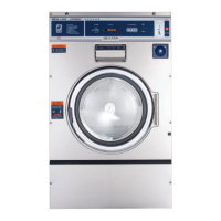
Drive Belt Removal
Turn the drive pulley while applying pressure to
the drive belt until it rolls off of the basket pulley
rst and then remove from the motor pulley. Be
cautious not to drop the motor which could unhook
the tension assembly.
Reverse this procedure for installation.
Door Lock Gear Motor
Thermoactuators
Drive Belt
78 79
Part # 8533-080-001 12/15 Part # 8533-080-001 12/15
 Loading...