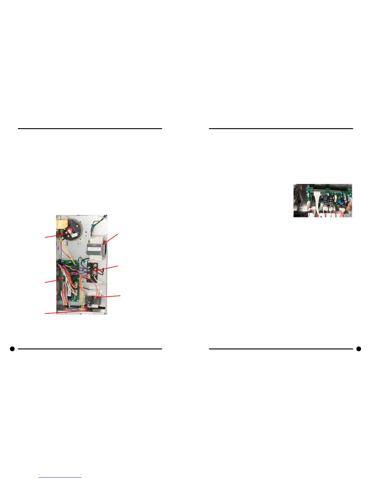
Control Mounting Trough
Remove top panel to access control trough. (see Removing Top Panel) It sets on the right side of the
machine and holds the control PCB’s, transformers,and pressure switch.
Controls Transformer
This transformer is mounted at the back of the control trough and steps a range of 208 to 240 volts down
to 120 volts for the controls. There are two terminals on the controls transformer for incoming power. One
terminal tap is marked for L1 208 volts use this tap for measured voltage of 200 volts - 219 volts. and the
other tap is marked L1 240 volts for 220 volts - 240 volts. Note: All washers have a controls transformer.
Always check the incoming voltage and use the appropriate transformer terminal when installing ALL
washers.
Circuit Breaker/Fuse
The fuse (optional circuit breaker) mounts to the rear channel. It carries all of the controls in the machine
but does not include the motor. To reset the circuit breaker just push in the button. If you have a fuse
then remove fuseholder and fuse and replace with a 1 1/2 amp fast blow type fuse.
Power Connection Terminal Block
This terminal block sets at the very back of the control trough on the T-300 models and is behind the
removable electrical panel on the back of all other machines. Incoming power to the washer should
connect here. (see Electrical under Installation and Operation Section for exact connections)
Controls Transformer
Power Connection
Terminal Block
Main Relay
Board
Fuse
Pressure
Switch
PCB Transformer
PCB Transformer Step-down
Small transformer mounted at front of control trough that is powered with 120 VAC primary and 24VAC on
the secondary side.
Main Relay Printed Circuit Board
Please be sure to be grounded to machine before removal of this board. PCB mounting horizontal in
control trough towards front of machine. Remove 4 mounting nuts.
Main Control Printed Circuit Board
Please be sure to be grounded to machine before removal
of this board from machine. PC board mounted vertically
behind front control panel. Remove hold down nuts in 4
corners and 1 at bottom center.
Main LED Printed Circuit Board Temperature & Start Display/Push-Button
The selector switch is mounted in the center of the control panel and is held in place with ve nuts. It
allows the selection of hot, warm or cold water temperatures. Note: Do not over tighten on reinstallation
as the switch can be damaged, stay pushed in and will cause erratic displays.
Emergency Stop Button Switch Assembly
The stop button is mounted on right side of machine. Remove the top and access the rear of button.
Remove the plastic retainer by unthreading CCW. The switch assembly will have to be removed by
pressing down on the plastic clip while pulling the switch body away from the stop button.
86 87
Part # 8533-080-001 12/15 Part # 8533-080-001 12/15
 Loading...