MAINTENANCE AND FAULT FINDING
EPT031055 Issue 2 September 2017 5-27
STATUS LEDS
Inside the controller, some LEDs display the status of the electronics.
On the DIB board directly on the front:
On the safety relay:
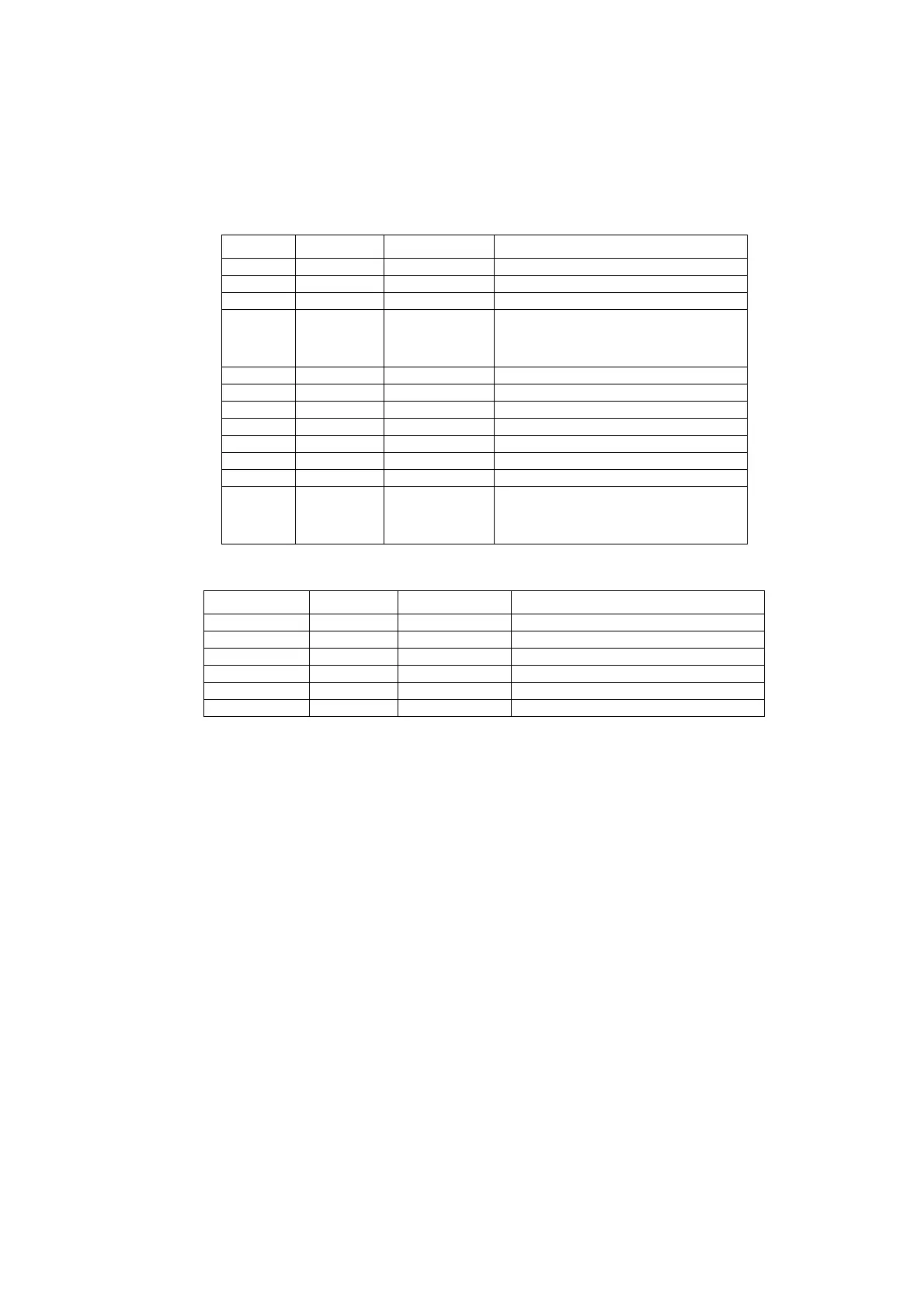
Name Colour Location Function
V6 green DIB-PCB Product Detect
V7 green DIB Mark suppress Control
V8 green DIB Encoder Channel A
V9 green DIB Laser Fan Frequency
When shutter active “shutter
open”
V10 yellow DIB Laser Modulation
V11 red DIB Laser Error
V12 yellow DIB Bypass Relay Power Supply
V13 green DIB Encoder Channel B
V14 yellow DIB Mains Wave pos. AC
V15 yellow DIB Mains Wave neg. AC
V16 green DIB Ready Chain FB
V17 yellow DIB All static “Laser start” signals,
e.g. key switch, external laser
start etc.
Name Colour Location Function
LED Power green Safety Relay Supply voltage
LED In1 green Safety Relay Input status, channel 1
LED In2 green Safety Relay Input status, channel 2
LED Out green Safety Relay Switch status, safety contacts
LED Reset green Safety Relay Reset circuit
LED Fault red Safety Relay Error
 Loading...