INSTALLATION INSTRUCTIONS
2-52 EPT031055 Issue 2 September 2017
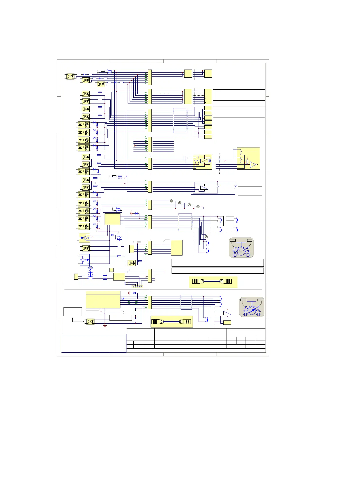
CONNECTOR OVERVIEW
1
1
2
2
3
3
4
4
H H
G G
F F
E E
D D
C C
B B
A A
Date Name Date Name
Ind. Chan.No. Changing Processed Reviewed
Title:
Project:
No.: 124714
BCP7 Electrical Connections
Valid from SCI 3.30 with fiber laser
bcp7_electrical_connections-1_07-124714b.SchDoc
Date
See box
File:
Version: See box Page of Size: A311
D-22547 Hamburg
Germany
Domino Laser GmbH
Fangdieckstraße 75a
© Domino Laser GmbH
A 1.00 created 28.02.12 PKU
A 1.01 X4 Description
23.10.12 PKU
A 1.02 added : values of the input resistors 25.10.12 PKU
A 1.03 add : mains power connection 110V /
230V 15.01.13 PKU
A 1.04 without Cat2, new:Cat3=PL_d; Cat4=PL_e (Performance-Level...) 26.03.13 MAU
a05: Including Interlock X69 (shutter /fiber laser version)
13.02.14
HK/PKU
a06 change externe signal designation / remove interne s.d. 24.06.14 PKU
b07 3.30 corr (fiber only: X29 > X69, lock coil diode) 17.11.14 HK
\\emea\group\Sator\R&D\Private\Elektronics\design\systems\bcp\bcp7\docu\bcp7_electrical_connections
1
2
3
4
5
6
7
X69
Laser Start
Print Go
L1_SOURCE
PRINT_GO
IL1_INP
PRINTER READY OUTPUT
EXT_LSTART_IN
Printer Ready
3
1
4
5
6
2
7
WH
BN
GN
YE
GY
PK
BU
PL_d PL_e
5
1
3
4
1
3
5
A
B
C
D
E
F
G
H
J
K
L
M
X4
1
2
3
4
5
6
7
8
X6
1
2
3
4
5
6
7
8
X3
100R
PD input
Enc A input
Enc B input
In order to use the shaft encoder as a print-go source ensure that pins 3
and 4 are connected.
WARNING: In this configuration no additional
product detector should be connected.
LASER_START
4K4
MARK_CONTROL
4K4
PRINT GO
4K4
PROG IN
4K4
PRINTER_READY
PRINTER_BUSY
COMPILE_OK
Logic Input
Logic Input
Logic Input
Logic Input
Logic Output
Logic Output
Logic Output
DCinputs: 10-30V/Rin 2,2K
DC outputs max 24V /max 500mA
Machine Interface X4
+
-
PLC
Output
+
-
PLC
Output
+
-
PLC
Output
+
-
PLC
Output
+
-
PLC
Input
+
-
PLC
Input
+
-
PLC
Input
INP_COM
LASER_START
MARK_CTRL
PRINT_GO
PROG_IN
OUT_+COM
PRINTER_READY
PRINTER_BUSY
COMPILE_OK
NC
+ Supply
0V
A
B
Z
+ Supply
0V
A
B
Z
Z
A
B
PNP
Encoder
Input mode
Differential (Standard)
Encoder
Input mode
2
3
4
5
6
7
8
1
2
3
4
5
6
7
8
1
*
Shaft Encoder Input X6
*
*
*
Product Detect Interface X3
PNP
+ Supply
0V
Q
1
2
3
4
NPN
+ Supply
0V
Q
1
2
3
4
PD+ Product Detect positiv input
+24V floating, max 120mA
GNDF - floating Ground
CustomerBCP7 Controller
GND
+24V
GND
+24V
*
1
2
3
4
5
X2
Logic Output
Logic Output
Logic Output
Logic Output
GND
+24V
BLUE (+24V output)
Beacon Interface X2
Blue
Amber
Green
Red
1
2
3
4
5
6
X28
4K4Input Air OK
4K4Input Chiller OK
Output Air/Chiller ON
AIR_OK
CHILLER_OK
CHILLER_AIR_ON_+COM
Air/Chiller Control X28
1
2
3
4
5
6
X7
4K4Input Vacuum OK
4K4Input Filter OK
Output Exhauster ON
VAC_OK
FILTER_OK
VAC_ON_+COM
VAC_ON_NO
Exhauster with Relay
+
Exhauster with Logic Input
GND
2
1
3
4
5
6
Vacuum Control X7
GND
1
2
3
4
5
6
7
8
X23
RTS - Request to Send
CTS - Clear to Send
DTR - Data Terminal Ready
GND - Ground
DSR - Data Set Ready
RXD - Receive Data
TXD - Transmit Data
DCD - Data Carrier Detect
RS232 Interface X23
Pilz PNOZ S4
PL_ePL_d
mode
In2+ In2-
AA
WH
BN
GN
YE
GY
PK
BU
RD
BK
VT
GY-PK
RD-BU
X58 is only suitable for controller interconnection. X58 is needed to connect the power extension box for
D620i systems. Do not connect anything else to this connector!
Depends on Dynamark options!
Default Air/Chiller Control X28
Laser ON = Air ON
Laser ON = Chiller ON
Air OK respectively
water level OK!
Chiller OK!
The main cable controller to laser is available in two versions:
Main cable BCP7 Cheetah / Harting-plug
Main cable BCP7 Cheetah / Toughcon-plug
1K
100R1K
100R1K
Ethernet 2 (Remote Panel Interface) X59
1
2
3
4
5
6
7
X59
TX+_Transmit+
TX-_Transmit-
RX+_Receive+
RX-_Receive-
LSTART_INP
Remote Panel
Power Input
for future application
S11
S12
S21
S22
Pilz PNOZ S4
A2A1
Printer Ready Output
N.C.
N.C.
Laser start Input
PG/ Trigger Input
Opto Coupler
GND
+24V
4K4
2K2
ETH Control
GND
+24V
TX+
TX-
RX+
RX-
4K7
Logic Input
1
2
3
4
5
PE
N
PE
BN
BU
GN/YE
RD
BK
EXT_L_PWR+
EXT_L_PWR-
1
2
Molex MiniFit SR-2
AC Power line (110/230V)
Harting HAN 3A/5
600V/16A
BU
BN
N
L
BU
BN
2B
1A
2A
1B
1
2
3
DIB-X5
Sabre-3
L
N
PE
PE Housing
PE Chassis
F1
F2
EXT_L_PWR
L-out
N-out
PE
L-in
N-in
GN/YE
GN/YE
GN/YE
GN/YE
1
2
3
4
5
6
7
X69
Laser Start
IL1_SOURCE +24V
IL1_INP
EXTERNAL LASER START INPUT
3
1
4
5
6
2
7
WH
BN
GN
YE
GY
PK
BU
PL_e
Pilz PNOZ S4
PL_ePL_d
mode
In2+ In2-
AA
Pilz mm0p
Programmed with shutter feedback verification
Safety 1 source
Safety 1 feedback
PSU 24V
+
-
4
3
1
2
U5
PC357N2TJ00F
Filter / input ref.1.6V /
start logic / driver
Via X68 to:
CP7 / X29 (floating
system)
To laser and board supply
X29X68
BCP7 ControllerFb-Laser Extension Box
DLG: 122383
Connect this cable for the shutter function
Door lock output
X24
X24
BCP7 ControllerFb-Laser Extension Box
DLG: 122384
Install this cable for the fiber laser internal data connection.
L2_GND
IL2_INP
DOOR LOCK OUTPUT
IL2 (a)
IL2 (b)
IL2 (a)
IL2 (b)
GND / PE
+
-
PLC
Output
7
2
6
Laser Start
Door lock (optional)
Interlock X69 (shutter version)
2.10 3.00
2.10 3.00
PD- Product Detect negativ input
PD+ Product Detect positiv input
+24V floating, max 120mA
GNDF - floating Ground
PD- Product Detect negativ input
CHA+ Encoder Channel A positiv input
CHB+ Encoder Channel B positiv input
CHA- Encoder Channel A negativ input
CHB- Encoder Channel B negativ input
+24V floating
GNDF - floating Ground
GNDF - floating Ground
+24V floating
GNDF - floating Ground
CHILLER_AIR_ON_NO
+24V floating
GNDF - floating Ground
AMBER (+24V output)
GREEN (+24V output)
RED(+24V output)
+24V floating
GNDF - floating Ground
L
Interlock X69 (NO shutter version)
Case GND
Case GND
 Loading...