SC-F2000 Revision C
DISASSEMBLY & ASSEMBLY Disassembly and Assembly Procedure 107
Confidential
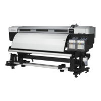
8. Remove the DAMPER KIT with the TUBE ASSY.
Figure 3-55. Removing the DAMPER KIT (2)
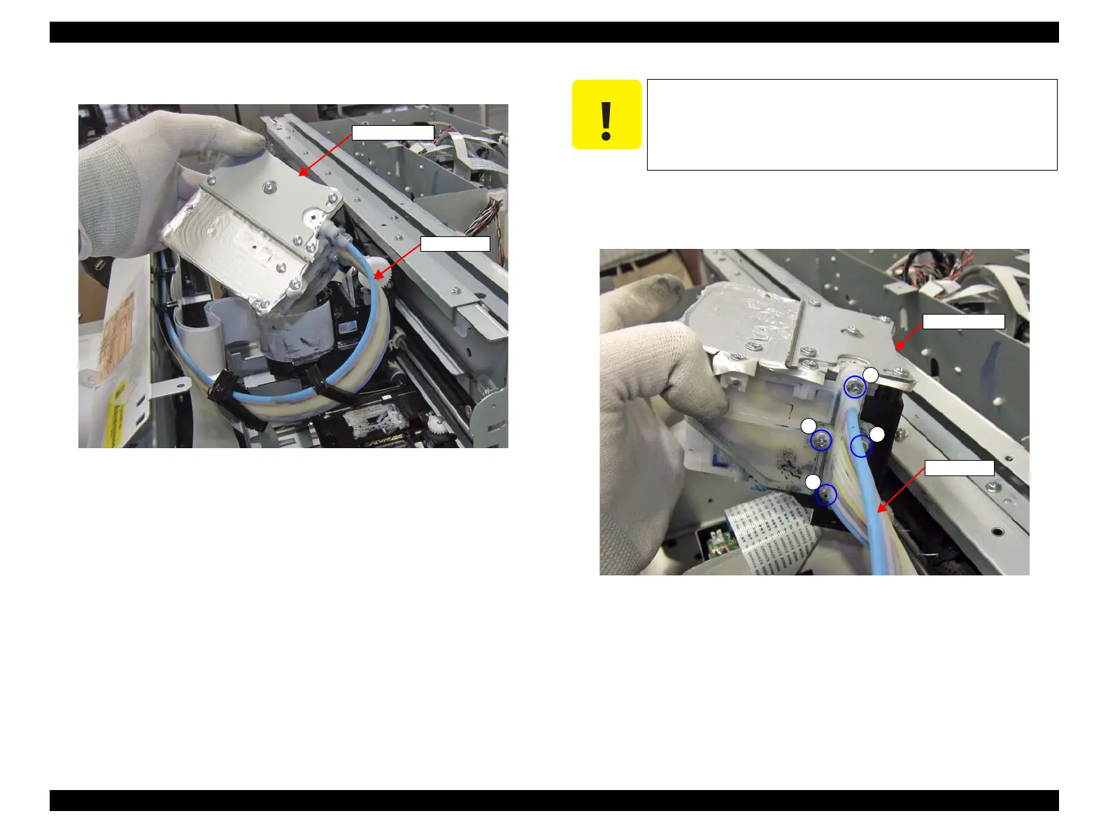
9. Remove the four screws, and remove the DAMPER KIT from the TUBE ASSY.
D) Silver M3x10 Bind machine screw: 4 pcs
Figure 3-56. Removing the DAMPER KIT (2)
When the TUBE ASSY is removed at the following step, ink
may drip off from the tube. Prepare a waste cloth in advance
and be careful not to contaminate the surroundings.
When removing the screw D, do not place the DAMPER KIT
lower than the CR UNIT. Otherwise ink may leak.
 Loading...