SC-F2000 Revision C
DISASSEMBLY & ASSEMBLY Disassembly and Assembly Procedure 188
Confidential
3.4.7 Fans
3.4.7.1 BOARD BOX FAN 1
1. Remove the PRINTER COVER. (p72)
2. Remove the RIGHT HOUSING PLATE. (p74)
3. Remove the RIGHT COVER ASSY. (p88)
4. Remove the LEFT HOUSING PLATE. (p73)
5. Remove the LEFT COVER ASSY. (p86)
6. Remove the REAR COVER SUB ASSY. (p77)
7. Remove the REAR COVER. (p79)
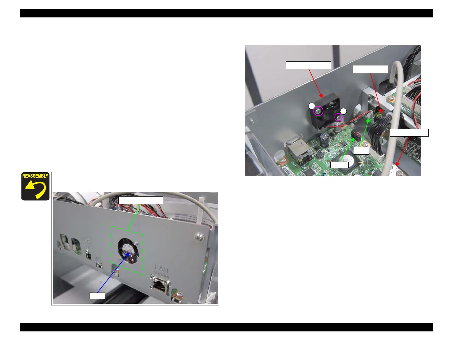
8. Disconnect the cable from the connector (CN10) of the MAIN BOARD.
9. Disconnect the cable from the connector (CN701) of the MAIN-B BOARD.
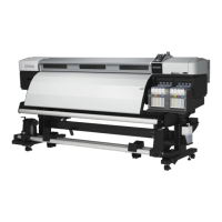
10. Remove the two screws, and remove the BOARD BOX FAN 1.
A) Silver M3x14 Bind machine screw: 2 pcs
Figure 3-154. Removing the BOARD BOX FAN 1
Install the BOARD BOX FAN 1 so that the Label comes to the
outside.
BOARD BOX FAN 1
A
A
MAIN BOARD
CN10
MAIN-B BOARD
CN701
 Loading...