SC-F2000 Revision C
DISASSEMBLY & ASSEMBLY Disassembly and Assembly Procedure 95
Confidential
3.4.4 Electric Circuit Components
3.4.4.1 MAIN BOARD
1. Remove the PRINTER COVER. (p72)
2. Remove the RIGHT HOUSING PLATE. (p74)
3. Remove the RIGHT COVER ASSY. (p88)
4. Remove the LEFT HOUSING PLATE. (p73)
5. Remove the LEFT COVER ASSY. (p86)
6. Remove the REAR COVER SUB ASSY. (p77)
7. Remove the REAR COVER. (p79)
8. Remove the SUB-B BOARD. (p98)
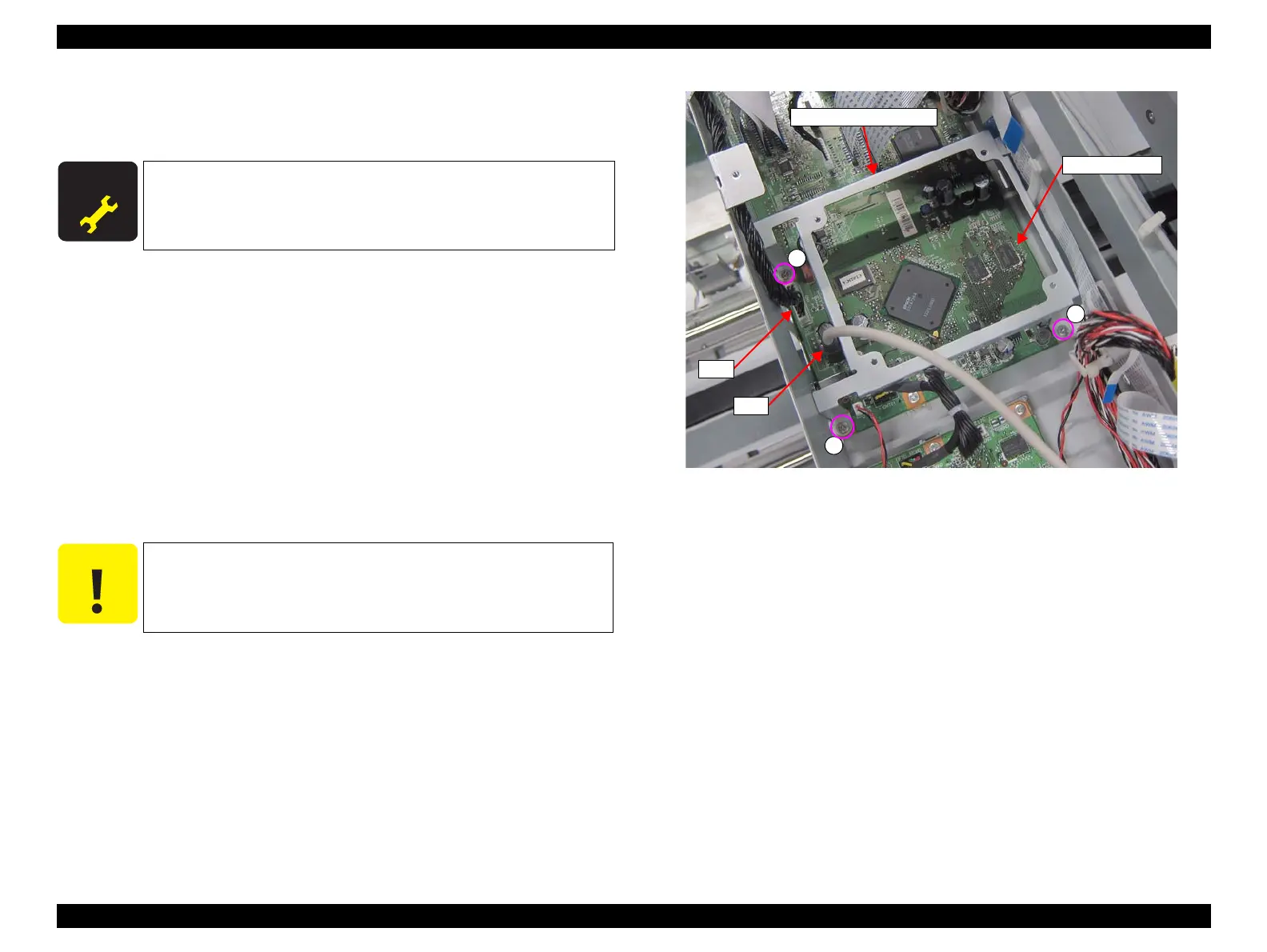
9. Disconnect the cables from the connectors (CN1, CN7) of the MAIN BOARD.
10. Remove the three screws, and remove the P.C.B Relay Fixing Plate.
A) Silver M3x8 Bind machine screw: 3 pcs
Figure 3-41. Removing the P.C.B Relay Fixing Plate
A D J U S T M E N T
R E Q U I R E D
When replacing/removing this part, refer to “4.1.2 Adjustment
Items and the Order by Repaired Part” (p194) and make sure to
perform the specified operations including required adjustment.
Remove the P.C.B Relay Fixing Plate taking care not to damage the
cables.
A
A
A
P.C.B Relay Fixing Plate
CN1
CN7
MAIN BOARD
 Loading...