SC-F2000 Revision C
DISASSEMBLY & ASSEMBLY Disassembly and Assembly Procedure 183
Confidential
3.4.6.11 TF ENCODER BOARD ASSY
1. Remove the REAR COVER SUB ASSY. (p77)
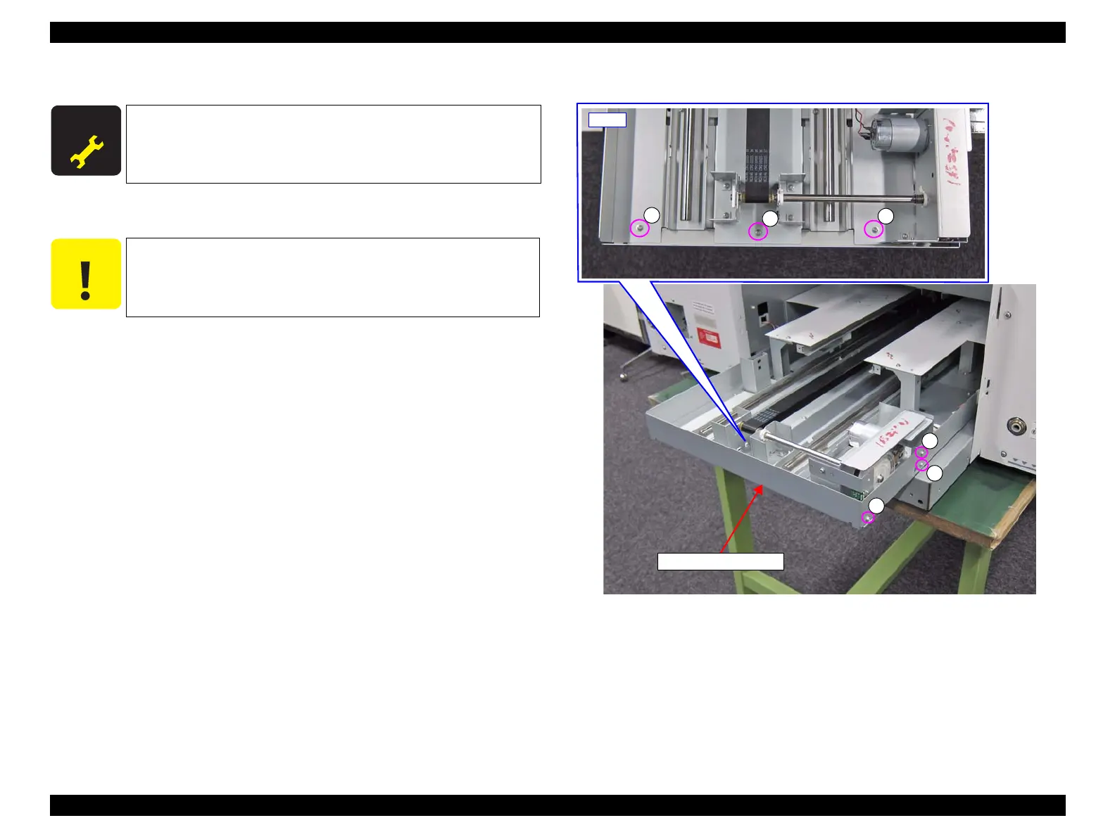
2. Remove the six screws, and remove the Rear Bottom Sub Frame.
A) Silver M3x6 Cup S-tite screw: 6 pcs
Figure 3-148. Removing the Rear Bottom Sub Frame
A D J U S T M E N T
R E Q U I R E D
When replacing/removing this part, refer to “4.1.2 Adjustment
Items and the Order by Repaired Part” (p194) and make sure to
perform the specified operations including required adjustment.
Be sure to remove the REAR COVER SUB ASSY while supporting
it with your hand because the REAR COVER ASSY will drop if the
screws are removed.