T3-B T6-B Manipulator 11. EMERGENCY
T-B series Rev.1 107
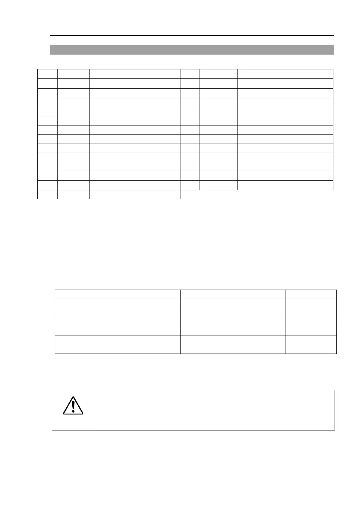
11.3 Pin Assignments
The EMERGENCY connector pin assignments are as follows: (D-Sub 25 pin male)
Emergency Stop switch contact (1)
*3
Emergency Stop switch contact (2)
*3
Emergency Stop switch contact (1)
*3
Emergency Stop switch contact (2)
*3
Emergency Stop circuit 1 (+)
*4
Emergency Stop circuit 2 (+)
*4
Emergency Stop circuit 1 (-)
*4
Emergency Stop circuit 2 (-)
*4
*1
*1
*2
*2
*2
*2
*1
*1 Do not connect anything to these pins.
*2 A critical error occurs if the input values from the Safeguard 1 and Safeguard 2 are
different for two or more seconds. They must be connected to the same switch with
two sets of contacts.
*3 A critical error occurs if the input values from the Emergency Stop switch contact 1
and Emergency Stop switch contact 2 are different for two or more seconds. They must
be connected the same switch with two sets of contacts.
*4 Do not apply reverse voltage to the Emergency Stop circuit.
Emergency Stop switch output rated load
Emergency Stop rated input voltage range
Emergency Stop rated input current
+24 V ±10%
37.5 mA ±10% /+24 V input
3-4, 16-17 pin
Safeguard rated input voltage range
Safeguard rated input current
+24 V ±10%
7-8, 20-21 pin
Latch Release rated input voltage range
Latch Release rated input current
+24 V ±10%
18-19 pin
The total electrical resistance of the Emergency Stop switches and their circuit should be 1
Ω or less.
CAUTION
The 24 V output is for emergency stop.
Do not use it for other purposes. Doing so
may result in system malfunction.
Do not apply reverse voltage to the Emergency Stop circuit.
Doing so may result
NOTE
 Loading...


