T3-B T6-B Manipulator 3. Environments and Installation
48 T-B series Rev.1
3.2 Base Table
A base table for anchoring the Manipulator is not supplied. Please make or obtain the base
table for your Manipulator. The shape and size of the base table differs depending on the use
of the robot system. For your reference, we list some Manipulator table requirements here.
Base table is necessary for support not only the weight of the manipulator but also dynamic
motion when operating at the maximum acceleration/deceleration. Provides enough beams
to give sufficient strength.
The torque and reaction force produced by the movement of the Manipulator are as follows:
Max. Reaction torque on the horizontal plate
Max. Horizontal reaction force
Max. Vertical reaction force
The threaded holes required for mounting the Manipulator base are M8. Use mounting bolts
with specifications conforming to ISO898-1 property class: 10.9 or 12.9.
For dimensions, refer to “3.3 Mounting Dimensions”.
The plate for the Manipulator mounting face should be 20 mm thick or more and made of
steel to reduce vibration. The surface roughness of the steel plate should be 25 μm or less.
The table must be secured on the floor or wall to prevent it from moving.
The Manipulator installation surface should have a flatness of 0.5 mm or less and an
inclination of 0.5° or less. If the flatness of the installation surface is improper, the base may
be damaged or the robot may not fully show its performance.
When using a leveler to adjust the height of the base table, use a screw with M16 diameter
or more.
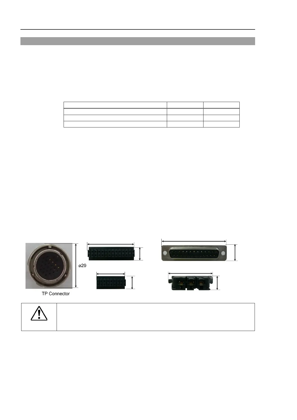
If you are passing cables through the holes on the base table, see the figures below.
WARNING
■
To ensure safety, a safeguard must be installed
for the robot system. For details
on the safeguard, refer to the
1.5 Safeguard.
 Loading...


