
Do you have a question about the Epson T3 Series and is the answer not in the manual?
| Payload | 3 kg |
|---|---|
| Number of Axes | 4 |
| Programming Language | EPSON RC+ |
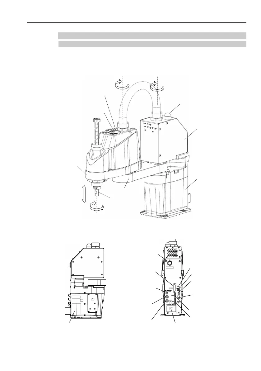
| Type | SCARA |
| Reach | 400 mm |
Covers safety precautions for personnel designing and installing robot systems.
Details conditions for safe robot system design including layout, end effector, and peripheral equipment.
Provides safety precautions for robot operators and general operation guidelines.
Details manipulator installation, environmental requirements, base table, and noise levels.
Explains EMERGENCY connector usage, safety switches, pin assignments, and circuit diagrams.
Covers power supply specifications, cable requirements, and step-by-step power-on procedures.
Provides instructions for installing the EPSON RC+ 7.0 software on the development PC.
Explains how to connect the development PC to the robot manipulator using a USB cable.
Details steps to check software setup and verify the connection between the PC and manipulator.
Guides users through creating and running a simple application program using EPSON RC+.


