2. Installation
56 Safety and Installation (T, VT / EPSON RC+ 7.0) Rev.15
2.4.4 Base Table
A base table for anchoring the Manipulator is not supplied. Please make or obtain
the base table for your Manipulator. The shape and size of the base table differs
depending on the use of the robot system. For your reference, we list some
Manipulator table requirements here.
The base table must not only be able to bear the weight of the Manipulator but also
be able to withstand the dynamic movement of the Manipulator when it operates at
maximum acceleration/deceleration. Ensure that there is enough strength on the
base table by attaching reinforcing materials such as crossbeams.
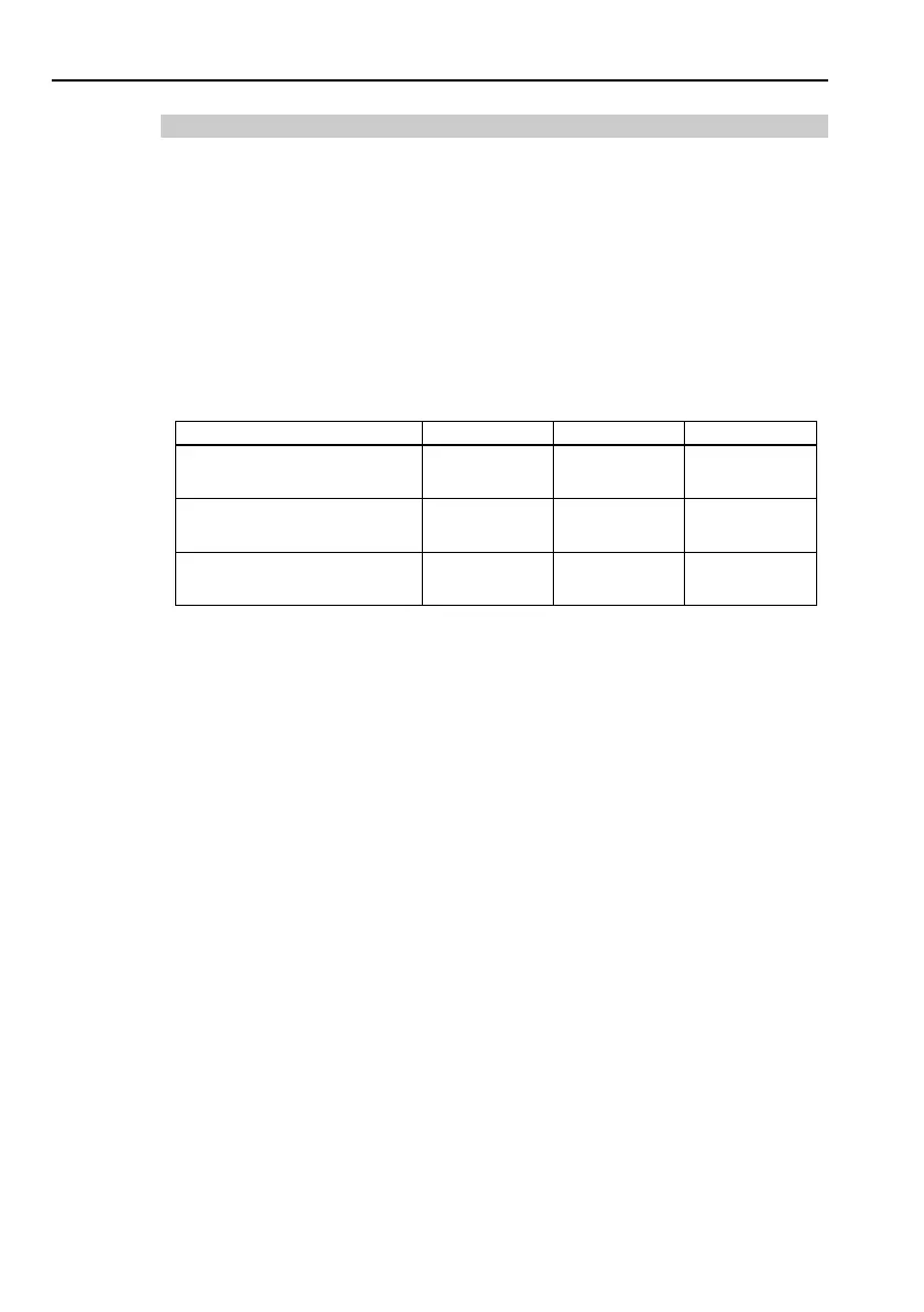
The torque and reaction force produced by the movement of the Manipulator are as
follows:
Max. Reaction torque on
150
150
500
Max. Horizontal reaction
force
500
500
500
Max. Vertical reaction
force
900
900
3100
The threaded holes required for mounting the Manipulator base are M8. Use
mounting bolts with specifications conforming to ISO898-1 property class: 10.9 or
12.9.
The plate for the Manipulator mounting face should be 20 mm thick or more and
made of steel to reduce vibration. The surface roughness of the steel plate should
be 25 μm or less.
The table must be secured on the floor or wall to prevent it from moving.
When mounting Manipulator on the mobile platform, be sure to use mobile platform
in low acceleration. If using the mobile platform in high acceleration, it may cause
Manipulator to make a safety stop.
Be sure to design the mounting position of Manipulator so that the center of gravity
is always within the mobile platform when Manipulator grasps a workpiece by using
a tool. For operation pose, create operation program so that the center of gravity
of Manipulator is always within the mobile platform. If the center of gravity is not
within the mobile flatform, Manipulator may fall over.
The Manipulator must be installed horizontally.
When using a leveler to adjust the height of the base table, use a screw with M16
diameter.
 Loading...


