5. System setting
5-1. Indoor unit setting
Setting Setting range Setting method
Set A
Indoor unit
Primary/Secondary
◌ “00” or “01”
Refer to Chapter 8-6. "Function details" on page
284. (Function number: 51)
Set B
Refrigerant circuit
address
● “00” to “15”
Refer to Chapter 8-6. "Function details" on page
284. (Function number: 02)
Set C
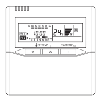
Remote controller
address
◌ “00” to “15”*
Refer to Chapter 8-6. "Function details" on page
284. (DIP switch setting)
NOTES:
• ◌: Setting is required.
• ●: By a case, setting is required.
• *: Set the remote controller address in the order of “00”, “01”, “02”,..., “15”. (Blank is not al-
lowed).
¢
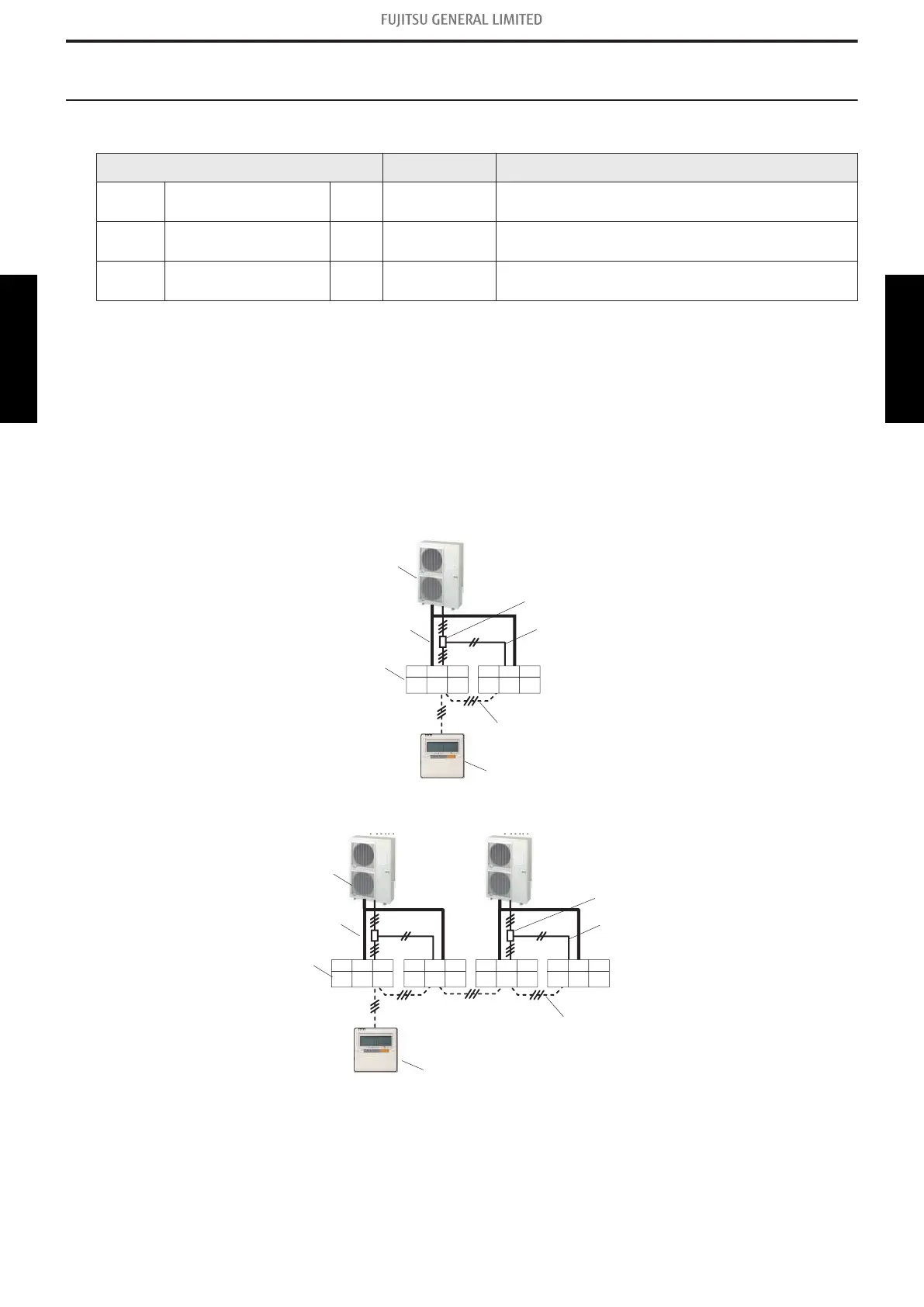
Twin type
• Connection example 1
Refrigerant pipe
Connection cable
Remote controller cable
SetASetB SetC
(00)(00)(00)
SetASetB SetC
01 01
(00)
<Twin>
Indoor unit
Outdoor unit
Wired remote controller
Junction box
• Connection example 2
Refrigerant pipe
Connection cable
Remote controller cable
SetASetB SetC
(00)
01 02
SetASetB SetC
01 01 03
SetASetB SetC
(00)(00)(00)
SetASetB SetC
01 01
(00)
<Twin> <Twin>
Indoor unit
Outdoor unit
Wired remote controller
Junction box
NOTE:
(00) is factory setting.
- 221 -
5-1. Indoor unit setting 5. System setting
SYSTEM
DESIGN
SYSTEM
DESIGN
 Loading...