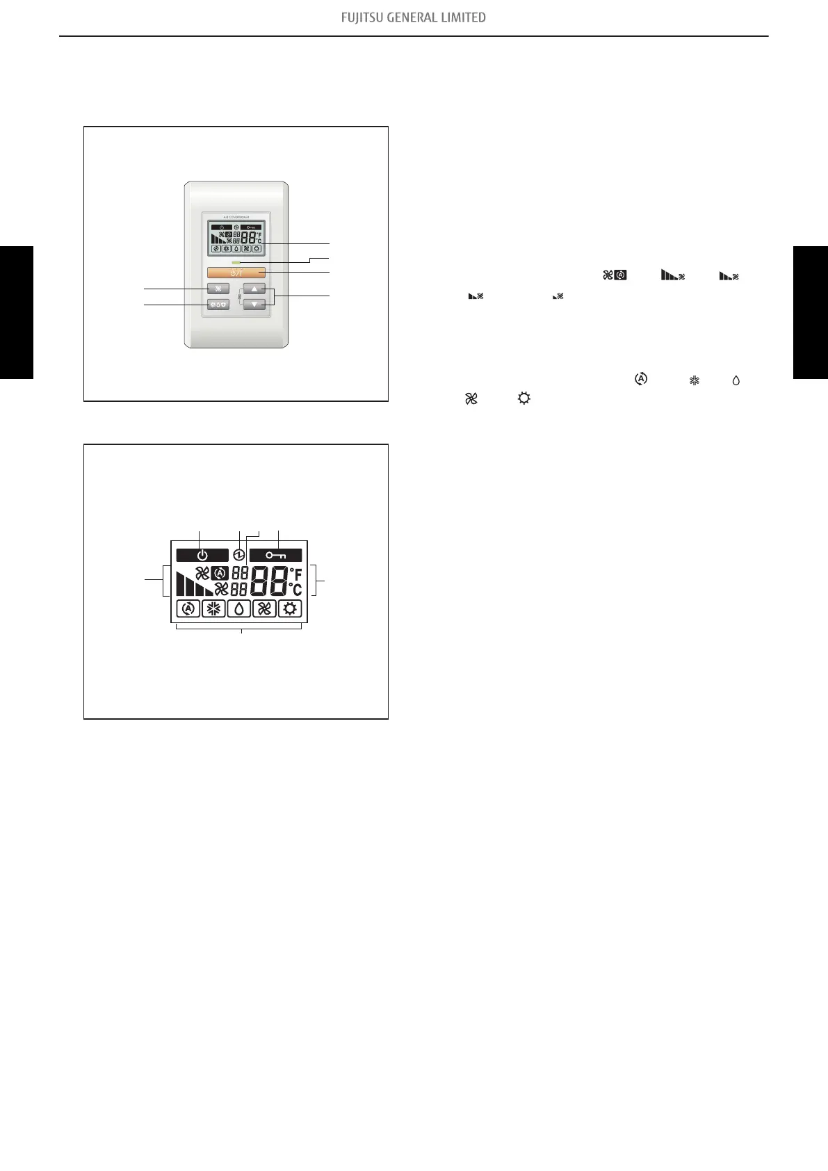
7-6. Simple remote controller (UTY-RSNYM: Optional part)
¢
Overview
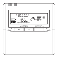
Display panel
a START/STOP button
Starts and stops operation.
b Display backlight button
Lights during operation.
c Operation lamp
Lights during operation.
d FAN button
Selects the fan speed (AUTO
,HIGH , MED ,
LOW , and QUIET ).
e SET TEMP. button
Selects the setting temperature.
f MODE button
Selects the operating mode (AUTO
, COOL , DRY ,
FAN , HEAT ).
g Standby indicator
Indicates during the oil recovery and defrosting operation.
h Power source indicator
Indicates the main power is on.
i Central control indicator
Indicates when function is locked.
j Fan speed indicator
Deletes the weekly timer schedule.
k Set temperature
• Indicates error history number in error code history dis-
play mode.
• Indicates indoor unit address in address display mode.
l Operating mode indicator
m Indicator
• Upper:
– Indicates the error code in error code history display
mode and in self diagnosis mode.
– Indicates the refrigerant system address in address
display mode.
• Lower: Indicates the remote controller address in error
code history display mode, address display mode, and
self diagnosis mode.
- 257 -
7-6. Simple remote controller (UTY-RSNYM: Optional part) 7. Remote controller
SYSTEM
DESIGN
SYSTEM
DESIGN
 Loading...