Home
Furuno
Marine Radar
FR-1505 MARK-3 Series
Furuno FR-1505 MARK-3 Series User Manual
5
of 1
of 1 rating
135 pages
Give review
Manual
Specs
To Next Page
To Next Page
To Previous Page
To Previous Page
Loading...
3-8
2.
Focus and Screen Volt
age
Bard Name
VR
Item
Remarks
SCREEN
Screen voltage
Adjusts screen volt
age
FO
CUS
H
Focus
voltage
Adjust
s focus of Horiz
ontal line
PG379
(Flyback Transforme
r)
FO
CUS
V
Focus volt
age
Adjusts f
ocus of Vertical line
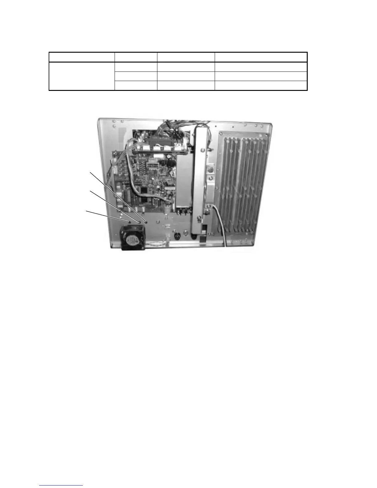
Figure
3.1
1
Display Unit,
rear view
FO
CUS
(
H)
FO
CUS
(
V)
SCREEN
54
56
Table of Contents
Default Chapter
3
Selection of Rectifier Unit
3
Remedy for Being Turned off at a Power-Up
4
Contents
5
Chapter 1. General
6
Major Specifications
6
Outline
6
Boards and Major Components
7
Display Unit
7
Scanner Unit
7
Specifications
8
Environmental Conditions
10
Power Supply & Power Consumption
10
Chapter 2. BLOCK DESCRIPTION
11
Overview
11
Simplified Block Diagram
11
Block Diagram of Display Unit
12
Function of each Board (Display Unit)
13
Process
15
Radar Start-Up Sequence
15
ARPA Start-Up Sequence
16
SPU Board Block Diagram
17
Video Signal Flow
18
Block Diagram of SPU Board
19
Auto Tuning Function
20
Tune Initialization
20
Auto/Maunal Tuning
21
Manual Tuning
21
Tuning Circuit
21
Tuning Indication
21
Video Adjustment
22
Echo Averaging (EAV 1/2/3)
23
Echo Stretch 1/2 and Enhanced Video
24
Normal/Enhanced Video Processing
24
Thin Trail
25
Trail Copy
25
Conventional Echo Trail Vs New Echo Trail
26
Clutter Sweep
27
Echo/Memory in Cluter Sweep Area
27
Clutter Sweep Picture
28
Normal Radar Picture
28
Frame Priority
29
Memories and Memory Name Priority
29
Memory Size
29
Antenna On/Off Circuit
30
Arp-10
30
ARP-15 Vs. ARP-17
30
Check of ARP and RP Board Connection
30
Simple ARPA Block Diagram
31
ARP-10 Block Diagram
32
Automatic Tracking
33
Conditions for Manual/Automatical Acquisition
33
Target Acquisition by Auto Plotter (ARP-10)
33
Target Discrimination
33
ARP-17 Block Diagram
34
ARPA Land Discrimination
35
ARPA Target Acquisition and Tracking (ARP-17)
35
Plot Menu 2
36
Start Time Target Vect
36
Target Select
36
Ttm
36
Block Diagram of RP Board
37
Input/Output Data To/From SPU Board
38
Input/Output of Main Panel Board
38
Input/Output Signal of ARP-17 Board/Arp-10
38
Sentences Receivable at J202 and J203
39
Radar and ARPA Output Signal from SPU Boards
40
CRT Required (Non-Interlace)
41
Monitor Signal from J103/J108
41
Video Signal
41
Block Diagram Power
42
DC Power Supply Circuit (03P9223)
42
Main/Sub-Inverter
42
Protector
42
DC Power Board
43
AC Power Supply Circuit
44
AC PWR Board
45
Gear Box
46
Radiator
46
RF Unit
46
Scanner Unit
46
Block Diagram of Scanner Unit
47
Chapter 3. Adjustment
48
Hazardous Voltage
48
Working on the Scanner Unit Mast
48
Adjustment (Display Unit)
49
Display Unit, Front/Bottom View
49
Location of Major Parts
49
Display Unit, Top/Rear View, Cover Removed
50
Lower Shield Cover Removed
50
Display Unit, Right-Side/Left-Side View, Cover Removed
51
Display Unit, Top/Left-Side View, SPU Board Removed
53
CRT Adjustment
54
CRT Size
54
To Back to Previous Menu
54
Display Unit, Rear View
55
Focus and Screen Voltage
55
Location of Parts on SPU
56
Test Points and Ratings
56
Location of Parts on ARP
57
Location of Parts on RP
59
Location of Parts on GYRO Board
60
Location of Parts on DC Power Board
61
Location of Parts on AC Power Board
62
Location of Parts on HV-9017 Board
63
Adjustment Scanner Unit
64
Antenna Radiator, Bottom View
64
Scanner Unit, Side View
64
Scanner Unit, Top View, Antenna Radiator Removed
64
Scanner Unit, Fore Side, Cover Removed
65
Scanner Unit, Stern Side, Cover and RF Module Removed
65
Scanner Unit, Stern Side, Cover Removed
65
RF Module, Top View/Bottom View
66
Location of Parts on if AMP
67
Location of Parts RFC
68
Location of Parts on Modulator
69
Fr-1510 Mark-3
70
Location of Parts on RFC
72
FR-1505 Mark-3
74
RF Module, Top/Bottom View
74
Chapter 4. Maintenace
76
Hazardous Voltage
76
Maintenance
76
DIP Switches
77
Jumper Settings
77
Connections on T1 on the 03P9223
78
LED Status Symbols
79
FR-1500M-3 Test
81
Self-Test
81
Test Menu
81
ARP Test
82
Ebl/Vrm/Trackball Test
82
Keyboard Test
82
Potentiometer Test
82
RP-17 Self-Test
83
Connection
84
How to Update System Program
84
Program Number
84
ARP Program
85
Arp-10/Arp-17
85
RP Program
85
Using Program Card/Disk
85
How to Store Default Setting
86
The Factory Menu
86
Magnetron
87
MIC
87
Notice on Replacing Major Parts
87
SPU Board
87
Chapter 5. Troubleshooting
88
Error Message
88
Troubleshooting Flow Charts
88
Visual Alarms
88
General Flow Charts
89
Symptom: Nothing Appears on the Display
90
Abnormal Display
91
No Heading Data
92
No Nav Data
93
Key Inoperative
94
Antenna Does Not Rotate
95
No Echoes nor White Noise
96
Poor Sensitivity
97
No GAIN, A/C SEA, A/C RAIN Effect
100
Target Cannot be Acquired
101
Chassis
102
Panel
103
Panel Assy
103
Right/Left Chassis
104
Cable Clamp Assy
105
Duct Case Assy
105
Rear Chassis Assy
105
Filter Assy
106
Power
106
Antenna Unit
107
Transceiver Unit
108
Schematic Diagrams
109
Marine Radar
110
Panel Board
113
TX-HV Board
114
AC Power Board
116
CRT Unit General
117
CPU and DSC Board
119
Video Sub Board
120
PWM CTL Board
121
CRT Socket Board
122
Filter Block
123
Processor Board
124
Modulator Board
127
RFC Board
128
IF AMP Board
129
Bearing Sig Gen Board
130
Electrical Parts List
131
5
Based on 1 rating
Ask a question
Give review
Questions and Answers:
Need help?
Do you have a question about the Furuno FR-1505 MARK-3 Series and is the answer not in the manual?
Ask a question
Furuno FR-1505 MARK-3 Series Specifications
General
Brand
Furuno
Model
FR-1505 MARK-3 Series
Category
Marine Radar
Language
English
Related product manuals
Furuno FR-1505
4 pages
Furuno FR-1500 MARK-3 Series
120 pages
Furuno FR-1510 MARK-3
120 pages
Furuno FR-1525 MARK-3
120 pages
Furuno FR-1510
135 pages
Furuno FR-1510D
110 pages
Furuno FR-2115
151 pages
Furuno FR-2155
152 pages
Furuno FR-2125V
138 pages
Furuno FR-2165DS
92 pages
Furuno FR-2115/2125
79 pages
Furuno MARINERADAR FR-8122
129 pages
 Loading...