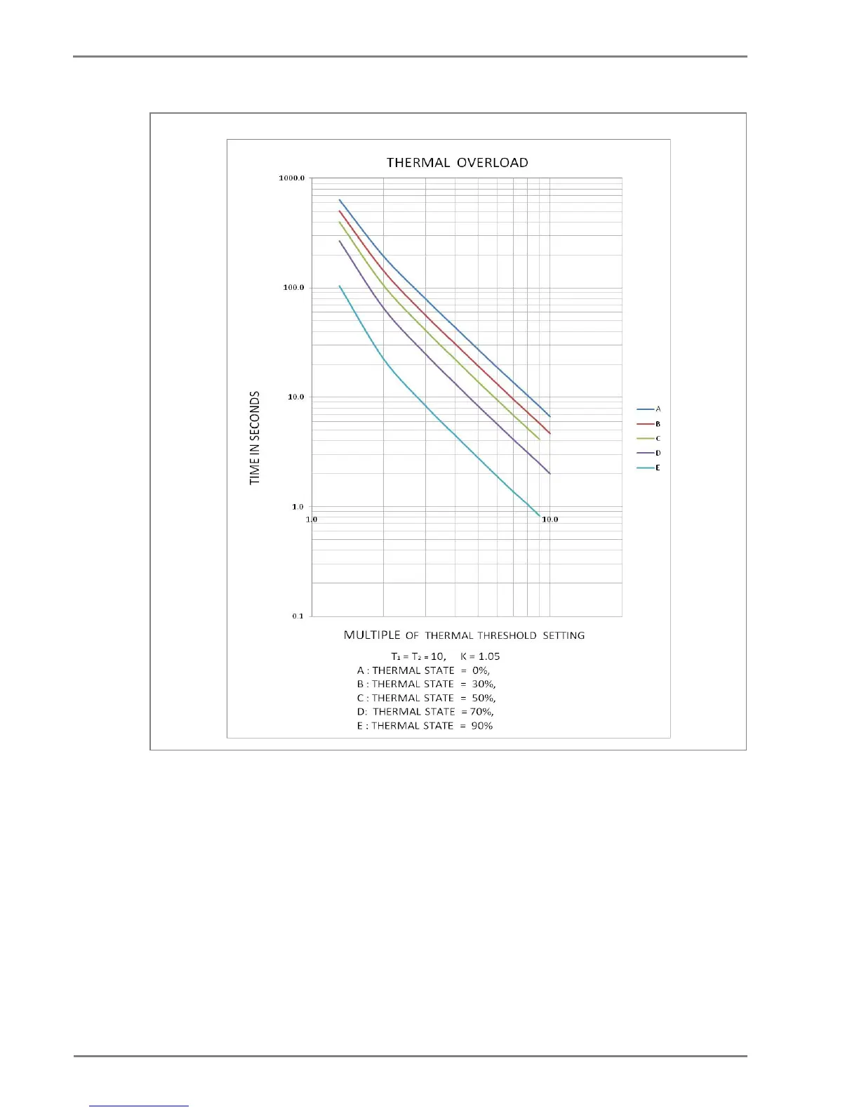
Figure 6: Thermal Overload curve
2.3.3 Thermal Overload Protection Implementation
The device incorporates a current-based thermal characteristic, using fundamental load current to
model heating and cooling of the protected plant. The element can be set with both alarm and trip
stages.
Thermal Overload protection is implemented in the THERMAL OVERLOAD column of the relevant
settings group. The magnitudes of the three phase input currents are compared and the largest
magnitude is taken as the input to the thermal overload function.
Thermal over load function supports setting for alarm and trip stages. If the thermal overload function
is enabled and thermal state of the protected equipment exceeds the alarm threshold setting, the
alarm is issued and indicated by illuminated START LED on the relay front panel.
 Loading...


