2.3.3 Terminal Blocks
2.3.3.1 CT/Auxiliary Power/Input/ Output Connections
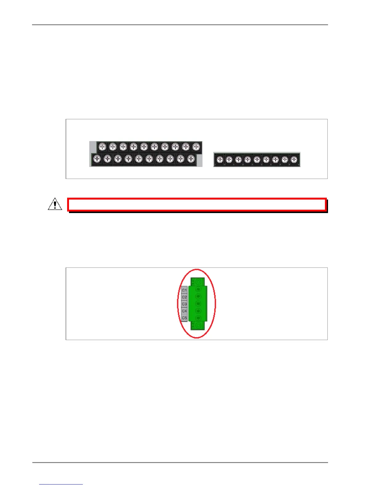
The P50 Agile devices use terminal blocks as shown below. The terminal block consists of up to 18 x
M5 screw terminals and 32 x M4 screw terminals. M5 terminal blocks are used for CT connections and
M4 terminal blocks are used for auxiliary power/input/output connections. The wires should be
terminated with rings using 90° ring terminals, with no more than two rings per terminal. The product is
supplied with sufficient M5 & M4 screws for proper connection.
Figure 6: Terminal blocks
Caution: Always fit an insulating sleeve over the ring terminal.
2.3.3.2 Rear Serial Port Connection
The rear serial port is intended for use with a permanently wired connection to a remote SCADA
system. The physical connectivity is achieved using three screw terminals: C3, C4 terminals for signal
connection, and C5 terminal for connecting cable shield. The terminal block is located at the rear of
the relay, as shown below.
Figure 7: Rear Serial port terminal block
2.3.3.3 Power Supply Connections
These should be wired with 1.5 mm PVC insulated multi-stranded copper wire terminated with M4 ring
terminals. The wire should have a minimum voltage rating of 300 V RMS.
If the auxiliary supply input of the relay needs to be wired then adequate care should be taken. See
the polarity marking on the terminal sticker at the rear of the relay for more information. The supply
range is also mentioned on the terminal sticker so before energising, care should be taken to confirm
that the auxiliary supply is wired within range.
 Loading...


