11 Commissioning Instructions
2.1.11.3 Performing the Test
1. Ensure the timer is reset.
2. Apply a current of twice the setting. This is shown in the I>1 Current Set cell in the
OVERCURRENT menu.
3. When the timer stops, make a note of the time displayed.
4. Check that the red trip LED has illuminated.
2.1.11.4 Checking the Operating Time
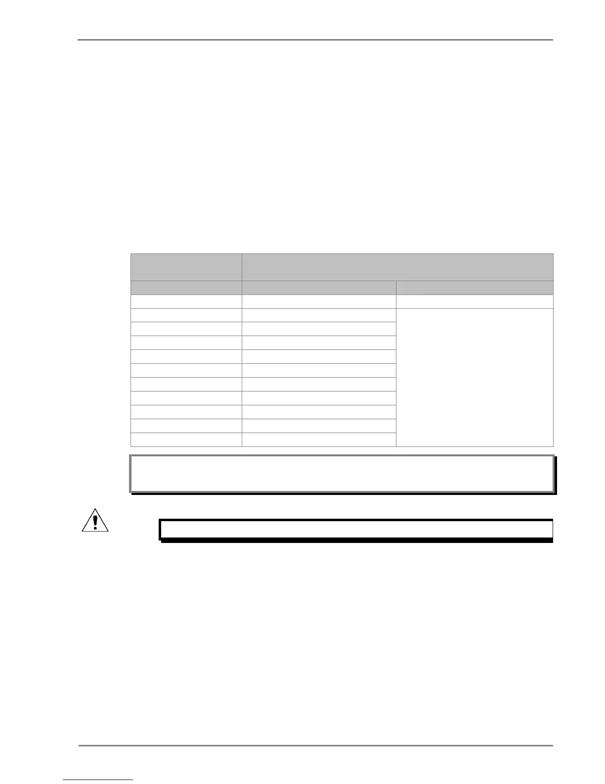
Check that the operating time recorded by the timer is within the range shown below.
For all characteristics, allowance must be made for the accuracy of the test equipment being used.
Characteristic
Operating time at twice current setting and time multiplier/
time dial setting of 1.0
Nominal (seconds) Range (seconds)
DT I>1 Time Delay setting Setting ±5% or 55ms whichever is greater
IEC S Inverse 10.03
Please refer to the Technical Specifications
chapter for operating time accuracy
IEC V Inverse 13.50
UK LT Inverse 20.00
IEEE M Inverse 3.8
IEEE V Inverse 7.03
IEEE E Inverse 9.50
Note: With the exception of the definite time characteristic, the operating times given are for a Time
Multiplier Setting (TMS) or Time Dial Setting (TDS) of 1. For other values of TMS or TDS, the values
need to be modified accordingly.
Caution: When the tests are complete, restore all settings that were disabled.
2.1.12 Thermal Overload Protection
The P253 relay models the time-current thermal characteristic of a motor by internally generating a
thermal replica of the machine. The aim of this test is to check:
• The presence of a thermal alarm as soon as the thermal state reaches the set threshold
• The time to a thermal trip in case of a thermal overload
• The measurements of the thermal load and thermal state
The settings of this function are listed in the THERMAL OVERLOAD, GROUP 1 menu column. Check
these settings before the test.
 Loading...


