disturbance records locally via the front panel LCD. This waveform can be downloaded via the
communication port for further analysis.
The fault recording is set by Trigger Position cell. The Trigger Position cell sets the trigger point as
a percentage of the duration.
The details of the disturbance record are as follows:
Capacity: 5 records of 1 sec each
Pre fault Trigger position: Programmable
Sampling rate: 16 samples / cycles
Triggers: Trip signals, external trigger via opto input assignment.
Data: 5 analogue channels and up to 37 digital channels (physical and logical
status).
2.2 Start-up Current Record
P253 relay records the starting current information every time the protected motor starts. This
information is very helpful in monitoring motor performance during the critical starting period. The
record can be downloaded using the P50 Agile configurator.
The details of the disturbance record are as follows:
Capacity: 1 records of 200 sec (max. duration)
Sampling rate: 1 sample / 5 cycles
Data: True RMS value, maximum value of one of the 3 phase currents
2.3 Record Control
The data stored in Event/Fault/Maintenance/Disturbance Records can be cleared by enabling the
settings Clear Events/Clear Faults/Clear Maint/Clear Dist Recs in Record Control menu. The
Thermal State can be reset by enabling the Thermal Reset setting.
2.4 Display of Measuring Parameters
The device directly measures and calculates a number of system quantities, which are updated at
regular intervals. These values can be viewed in the MEASUREMENTS menu on the LCD screen
using the navigation keys on the front panel or using the P50 Agile configurator tool.
In normal conditions the relay displays Primary and Secondary current value of phases A, B, C and
earth current N as per phase/earth CT ratio within ±2% accuracy and Thermal state in %.
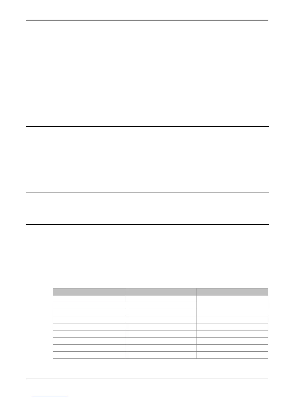
The device measures and displays the following quantities:
2.4.1 MEASUREMENT 1 Submenu
 Loading...


