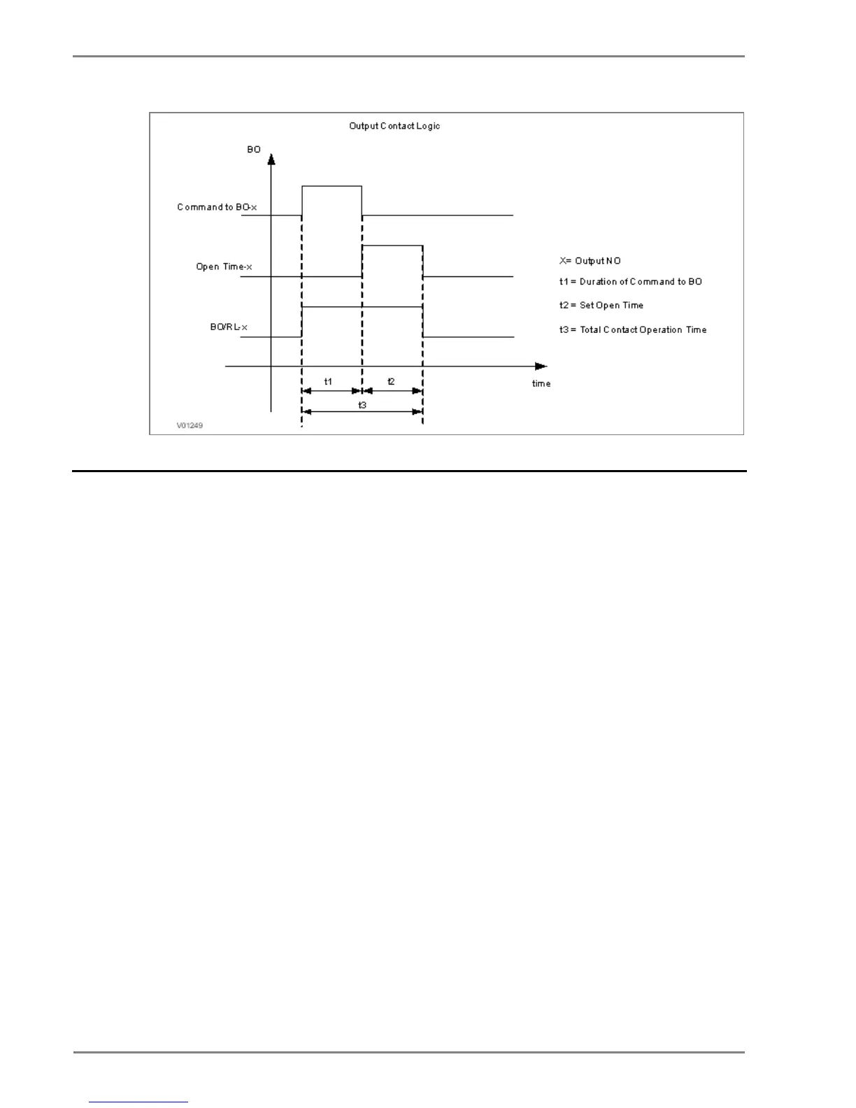
Figure 2: Output contact logic
2.7 Programmable LEDs
The device supports 4 numbers of programmable LEDs. All of the programmable LEDs on the unit are
bi-colour and can be set to RED or GREEN. The use of these LEDs depends on the application. There
are a number of settings associated with the relay outputs.
The programmable LEDs can be assigned to any available function. The programmable LEDs are
identified as L5 to L8. Different functions can be assigned by using P50 Configurator as well as relay
user interface. On the user interface, the LEDs can be assigned to any function from I/O
configuration menu. The function can be assigned to any input by entering the values to them either
0 or 1 i.e. 0 = not assigned and 1 = assigned.
The following diagram explains the assignment process of LEDs by either by UI or P50 Configuration.
Here G represents Green LED and R represents Red LED. Both are part of one command dual LED.
 Loading...


